CY7C68300B/CY7C68301B
CY7C68320/CY7C68321
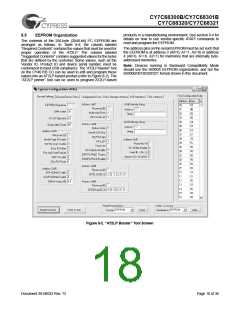
EEPROMs without an ATA/ATAPI device attached. If the ATA
Reset (ARESET#) line is LOW on power-up, the AT2LP will
enter Board Manufacturing Test Mode. A convenient way to
pull the ARESET# line LOW is to short pins 1 and 3 on the ATA
connector, which will tie the ARESET# line to the pull-down on
DD7.
In this mode, the AT2LP allows for reading from and writing to
the EEPROM, and for board level testing through vendor
specific ATAPI commands utilizing the CBW Command Block
as described in the USB Mass Storage Class Bulk-Only
Transport Specification. There is a vendor-specific ATAPI
command for the EEPROM access (CfgCB) and one for the
board level testing (MfgCB).
8.2
“No EEPROM Detected” Mode
8.4.1
CfgCB
When no EEPROM is detected at start-up, the AT2LP will
enumerate with VID/PID/DID values that are all 0x00, which is
not a valid mode of operation. These values can be factory
programmed into the AT2LP for high-volume applications to
avoid the need for an external EEPROM in some designs.
Contact your local Cypress Semiconductor sales office for
details.
The cfg_load and cfg_read vendor-specific commands are
passed down through the bulk pipe in the CBWCB portion of
the CBW. The format of this CfgCB is shown below. Byte 0 will
be a vendor-specific command designator whose value is
configurable and set in the configuration data (EEPROM
address 0x04). Byte 1 must be set to 0x26 to identify CfgCB.
Byte 2 is reserved and must be set to zero. Byte 3 is used to
determine the memory source to write/read. For the
CY7C68300B/CY7C68301B, this byte must be set to 0x02,
indicating the EEPROM is present. Bytes 4 and 5 are used to
determine the start address. For the CY7C68300B/301B, this
must always be 0x0000. Bytes 6 through 15 are reserved and
must be set to zero.
8.3
Normal Mass Storage Mode
In Normal Mass Storage Mode, the chip behaves as a USB 2.0
to ATA/ATAPI bridge. This includes all typical USB device
states (powered, configured, etc.). The USB descriptors are
returned according to the values stored in the external
EEPROM. An external EEPROM is required for Mass Storage
Class Bulk-Only Transport compliance, since a unique serial
number is required for each device. Also, Cypress requires
customers to use their own Vendor and Product IDs for final
products.
The data transferred to the EEPROM must be in the format
specified in Table 8-6 of this data sheet. Maximum data
transfer size is 255 bytes.
The data transfer length is determined by the CBW Data
Transfer Length specified in bytes
8
through 11
(dCBWDataTransferLength) of the CBW (refer to Table 8-1).
The type/direction of the command will be determined by the
direction bit specified in byte 12, bit 7 (bmCBWFlags) of the
CBW (refer to Table 8-1).
8.4
Board Manufacturing Test Mode
In Board Manufacturing Test Mode, the chip behaves as a
USB 2.0 device but the ATA/ATAPI interface is not fully active.
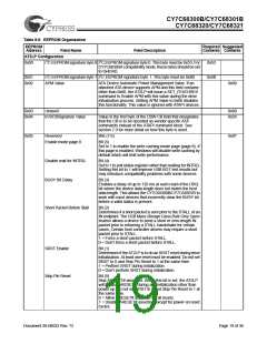
Table 8-1. Command Block Wrapper
Bits
Offset
7
6
5
4
3
2
1
0
0–3
4–7
DCBWSignature
dCBWTag
8–11 (08h–0Bh)
12 (0Ch)
dCBWDataTransferLength
bwCBWFLAGS
Dir
Obsolete
Reserved (0)
13 (0Dh)
Reserved (0)
Reserved (0)
bCBWLUN
bCBWCBLength
CBWCB (CfgCB or MfgCB)
14 (0Eh)
15–30 (0Fh1Eh)
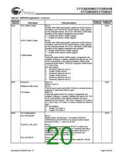
Table 8-2. Example CfgCB
Offset
CfgCB Byte Descriptions
Bits
7
0
0
0
0
0
0
0
6
0
0
0
0
0
0
0
5
1
1
0
0
0
0
0
4
0
0
0
0
0
0
0
3
0
0
0
0
0
0
0
2
1
1
0
0
0
0
0
1
0
1
0
1
0
0
0
0
0
0
0
0
0
0
0
0
1
2
3
4
5
bVSCBSignature (set in configuration bytes)
bVSCBSubCommand (must be 0x26)
Reserved (must be set to zero)
Data Source (must be set to 0x02)
Start Address (LSB) (must be set to zero)
Start Address (MSB) (must be set to zero)
6–15 Reserved (must be set to zero)
Document 38-08033 Rev. *D
Page 16 of 36

 CYPRESS [ CYPRESS ]