CY7C68300B/CY7C68301B
CY7C68320/CY7C68321
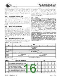
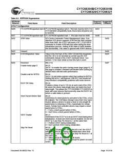
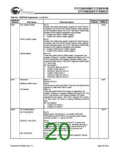
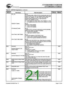
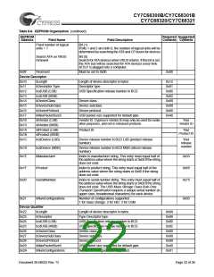
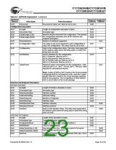
Table 8-6. EEPROM Organization
EEPROM
Required Suggested
Contents Contents
Address
Field Name
Field Description
AT2LP Configuration
0x00
I2C EEPROM signature byte 0 I2C EEPROM signature byte 0. This byte must be 0x53. For
CY7C68300A compatibility mode, these bytes should be set
to 0x4D4D.
I2C EEPROM signature byte 1 I2C EEPROM signature byte 1. This byte must be 0x4B
0x53
0x4B
0x01
0x02
APM Value
ATA Device Automatic Power Management Value. If an
attached ATA device supports APM and this field contains
other than 0x00, the AT2LP will issue a SET_FEATURES
command to Enable APM with this value during the drive
initialization process. Setting APM Value to 0x00 disables
this functionality. This value is ignored with ATAPI devices.
0x00
0x03
0x04
Unused
0x80
0x24
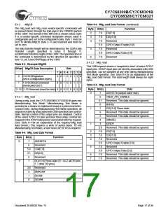
bVSCBSignature Value
Value in the first byte of the CBW CB field that designates
that the CB is to be decoded as vendor specific ATA
commands instead of the ATAPI command block. See
section 7.0 for more detail on how this byte is used.
0x05
Reserved
Bits (7:6)
0x07
Enable mode page 8
Bit (5)
Set to 1 to enable the write caching mode page (page 8). If
this page is enabled, Windows will disable write caching by
default which will limit write performance.
Disable wait for INTRQ
BUSY Bit Delay
Bit (4)
Set to 1 to poll status register rather than waiting for INTRQ.
Setting this bit to 1 will improve USB BOT test results but
may introduce compatibility problems with some devices.
Bit (3)
Enables a delay of up to 120 ms at each read of the DRQ
bit where the device data length does not match the host
data length. This allows the CY7C68300B/CY7C68301B to
work with most devices that incorrectly clear the BUSY bit
before a valid status is present.
Short Packet Before Stall
Bit (2)
Determines if a short packet is sent prior to the STALL of an
IN endpoint. The USB Mass Storage Class Bulk-Only Speci-
fication allows a device to send a short or zero-length IN
packet prior to returning a STALL handshake for certain
cases. Certain host controller drivers may require a short
packet prior to STALL.
1 = Force a short packet before STALL.
0 = Don’t force a short packet before STALL.
SRST Enable
Skip Pin Reset
Bit (1)
Determines if the AT2LP is to do an SRST reset during drive
initialization. At least one reset must be enabled. Do not set
SRST to 0 and Skip Pin Reset to 1 at the same time.
1 = Perform SRST during initialization.
0 = Don’t perform SRST during initialization.
Bit (0)
Skip ARESET# assertion. When this bit is set, the AT2LP
will bypass ARESET# during any initialization other than
power up. Do not set SRST to 0 and Skip Pin Reset to 1 at
the same time.
0 = Allow ARESET# assertion for all resets.
1 = Disable ARESET# assertion except for power-on reset
cycles.
Document 38-08033 Rev. *D
Page 19 of 36

 CYPRESS [ CYPRESS ]