CY7C68300B/CY7C68301B
CY7C68320/CY7C68321
ATAPI SFF-8070i commands to ATA commands for seamless
integration of ATA devices with generic Mass Storage Class
BOT drivers.
7.0
7.1
Functional Overview
USB Signaling Speed
7.2.1
ATA Command Block (ATACB)
AT2LP operates at the following two of the three rates defined
in the USB Specification Revision 2.0 dated April 27, 2000:
The ATA Command Block (ATACB) functionality provides a
means of passing ATA commands and ATA register accesses
to the attached device for execution. ATACB commands are
transferred in the Command Block Wrapper Command Block
(CBWCB) portion of the Command Block Wrapper (CBW).
The ATACB is distinguished from other command blocks by
having the first two bytes of the command block match the
bVSCBSignature and bVSCBSubCommand values that are
defined in Table 7-1. Only command blocks that have a valid
bVSCBSignature and bVSCBSubCommand are interpreted
as ATA Command Blocks. All other fields of the CBW and
restrictions on the CBWCB remain as defined in the USB Mass
Storage Class Bulk-Only Transport Specification. The ATACB
must be 16 bytes in length. The following table and text defines
the fields of the ATACB.
• Full-speed, with a signaling bit rate of 12 Mbits/sec
• High-speed, with a signaling bit rate of 480 Mbits/sec.
AT2LP does not support the low-speed signaling rate of 1.5
Mbits/sec.
7.2
ATA Interface
The ATA/ATAPI port on the AT2LP is compatible with the Infor-
mation Technology–AT Attachment with Packet Interface–6
(ATA/ATAPI-6) Specification, T13/1410D Rev 2a. The AT2LP
supports both ATAPI packet commands as well as ATA
commands (by use of ATA Command Blocks), as outlined in
Section 7.2.1. Refer to the USB Mass Storage Class (MSC)
Bulk Only Transport (BOT) Specification for information on
Command Block formatting. Additionally, the AT2LP translates
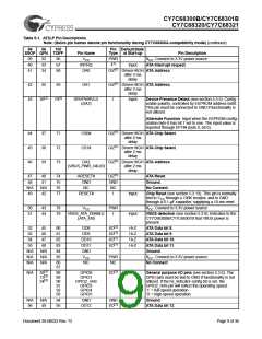
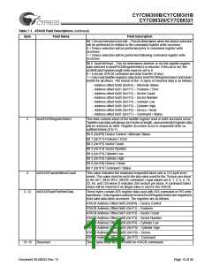
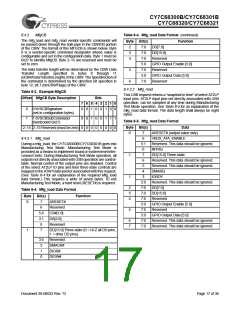
Table 7-1. ATACB Field Descriptions
Byte
Field Name
bVSCBSignature
Field Description
0
This fieldindicates to the CY7C68300B/CY7C68301B that theATACB contains
a vendor-specific command block. This value of this field must match the value
in EEPROM address 0x04 for this vendor-specific command to be recognized.
1
2
bVSCBSubCommand
bmATACBActionSelect
This field must be set to 0x24 for ATACB commands.
This field controls the execution of the ATACB according to the bitfield values:
Bit 7 IdentifyPacketDevice – This bit indicates that the data phase of the
command will contain ATAPI (0xA1) or ATA (0xEC) IDENTIFY device data.
Setting IdentifyPacketDevice when the data phase does not contain IDENTIFY
device data will result in unspecified device behavior.
0 = Data phase does not contain IDENTIFY device data
1 = Data phase contains ATAPI or ATA IDENTIFY device data
Bit 6 UDMACommand – This bit enables supported UDMA device transfers.
Setting this bit when a non-UDMA capable device is attached will result in
undetermined behavior.
0 = Do not use UDMA device transfers (only use PIO mode)
1 = Use UDMA device transfers
Bit 5 DEVOverride – This bit determines whether the DEV bit value is taken
from the value assigned to the LUN during start-up or from the ATACB.
0 = The DEV bit will be taken from the value assigned to the LUN during start-up
1 = The DEV bit will be taken from the ATACB field 0x0B, bit 4
Bit 4 DErrorOverride – This bit controls the device error override feature. This
bit should not be set during a bmATACBActionSelect TaskFileRead.
0 = Data accesses are halted if a device error is detected
1 = Data accesses are not halted if a device error is detected
Bit 3 PErrorOverride – This bit controls the phase error override feature. This
bit should not be set during a bmATACBActionSelect TaskFileRead.
0 = Data accesses are halted if a phase error is detected
1 = Data accesses are not halted if a phase error is detected
Bit 2 PollAltStatOverride – This bit determines whether or not the Alternate
Status register will be polled and the BSY bit will be used to qualify the ATACB
operation.
0 = The AltStat register will be polled until BSY=0 before proceeding with the
ATACB operation
1 = The ATACB operation will be executed without polling the AltStat register.
Document 38-08033 Rev. *D
Page 13 of 36

 CYPRESS [ CYPRESS ]