CY7C68300B/CY7C68301B
CY7C68320/CY7C68321
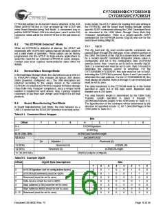
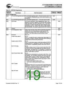
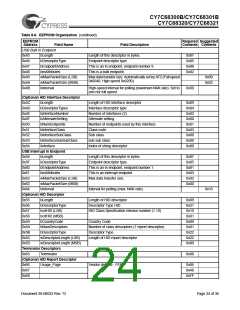
Table 8-6. EEPROM Organization (continued)
EEPROM
Address
Required Suggested
Contents Contents
Field Name
Field Description
0x06
ATA UDMA Enable
Bit (7)
0xD4
Enable Ultra DMA data transfer support for ATAPI devices.
If enabled, and if the ATAPI device reports UDMA support
for the indicated modes, the AT2LP will utilize UDMA data
transfers at the highest negotiated rate possible.
0 = Disable ATA device UDMA support.
1 = Enable ATA device UDMA support.
ATAPI UDMA Enable
Bit (6)
Enable Ultra DMA data transfer support for ATAPI devices.
If enabled, and if the ATAPI device reports UDMA support
for the indicated modes, the AT2LP will utilize UDMA data
transfers at the highest negotiated rate possible.
0 = Disable ATAPI device UDMA support.
1 = Enable ATAPI device UDMA support.
UDMA Modes
Bit (5:0)
These bits select which UDMA modes, if supported, are
enabled. Setting to 1 enables. Multiple bits may be set. The
AT2LP will operate in the highest enabled UDMA mode
supportedbythedevice. TheAT2LPsupports UDMA modes
2, 3, and 4 only.
Bit Descriptions
5
4
3
2
1
0
Reserved. Must be set to 0.
Enable UDMA mode 4.
Reserved. Must be set to 0.
Enable UDMA mode 2.
Reserved. Must be set to 0.
Reserved. Must be set to 0.
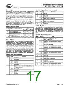
0x07
Reserved
Bits(7:3)
0x07
Must be set to 0.
Bit (2)
Multiword DMA mode
This bit selects multi-word DMA. If this bit is set and the drive
supports it, multi-word DMA is used.
Bits(1:0)
PIO Modes
These bits select which PIO modes, if supported, are
enabled. Setting to 1 enables. Multiple bits may be set. The
AT2LP will operate in the highest enabled PIO mode
supported by the device. The AT2LP supports PIO modes
0, 3, and 4 only. PIO mode 0 is always enabled by internal
logic.
Bit Descriptions
1
0
Enable PIO mode 4.
Enable PIO mode 3.
0x08
Pin Configurations
BUTTON_MODE
0x78
Bit (7)
Button mode. Set this bit to 1 to enable ATAPUEN,
PWR500# and DRVPWRVLD to become button inputs
returned on bits 2, 1, and 0 of EP1IN
SEARCH_ATA_BUS
BIG_PACKAGE
Bit (6)
Enables a search performed at RESET to detect non-
removable ATA and ATAPI devices. Systems with only a
removable device (like CF readers) will set this bit to 0.
Systems with one removable device and one non-
removable device will set this bit to 1.
Bit (5)
Package Select. Set this bit to 1 when using the 100-pin
device.
Document 38-08033 Rev. *D
Page 20 of 36

 CYPRESS [ CYPRESS ]