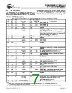
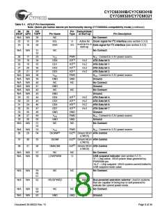
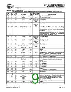
CY7C68300B/CY7C68301B
CY7C68320/CY7C68321
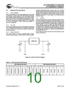
No
No
USB Interrupt
Pipe Polled?
SYSIRQ=1?
Yes
Yes
Latch State of IO Pins
Set Int_Data = 1
Yes
Int_Data = 1?
No
No
NAK Request
Yes
Int_Data = 0
and
SYSIRQ=0?
Return Interrupt Data
Set Int_Data = 0
Figure 5-7. SYSIRQ Latching Algorithm
5.3.5
DRVPWRVLD
• The status of the GPIO pins is also returned on the interrupt
endpoint (EP1) in response to a SYSIRQ. See section 5.3.3
for SYSIRQ details.
When this pin is enabled via EEPROM byte 8, bit 0, the AT2LP
will inform the host that a removable device, such as a CF
card, is present. The CY7C68300B/CY7C68301B will use
DRVPWRVLD to detect that the removable device is present.
Pin polarity is controlled by bit 1 of EEPROM address 8. When
DRVPWRVLD is deasserted, the AT2LP will report a “no
media present” status (ASC = 0x3A, ASQ = 0x00) to the host.
When the media has been detected again, the AT2LP will
report a “media changed” status to the host (ASC = 0x28,
ASQ = 0x00).
GPIO2_nHS also has an alternate function. If the “HS Indicator
Enable” configuration (bit 2 of EEPROM address 8) is set, the
GPIO2_nHS pin will reflect the operating speed of the device
(full- or high-speed USB).
5.3.7
LOWPWR#
LOWPWR# is an output pin that is driven to ‘0’ when the
AT2LP is active. LOWPWR# is placed in Hi-Z when the AT2LP
is in a suspend state.
When a removable device is used, it is always the master
device. Only one removable device may be attached to the
AT2LP. If the system only contains a removable device,
EEPROM byte 8, bit 6 must be set to ‘0’ to disable ATA device
detection at start-up. If a non-removable device is connected
in addition to a removable media device, it must be configured
as a slave (device address 1).
5.3.8
ATA Interface Pins
Design practices for signal integrity as outlined in the
ATA/ATAPI-6 Specification should be followed with systems
that utilize a ribbon cable interconnect between the
CY7C68300B/CY7C68301B’s ATA interface and the attached
ATA/ATAPI device, especially if Ultra DMA Mode is utilized.
DRVPWRVLD can also be configured as an input. See
Section 6.0 HID Functions for Button Controls.
5.3.9
VBUS_ATA_ENABLE
5.3.6
GPIO Pins
VBUS_ATA_ENABLE is typically used to indicate to the
AT2LP that power is present on VBUS. This pin is polled by
the AT2LP at start-up and then every 20ms thereafter. If this
pin is ‘1’, the internal 1.5K pull-up is attached to D+. If this pin
is ‘0’, the AT2LP will release the pull-up on D+ as required by
the USB specification. Also, If EEPROM byte 8, bit 4 is ‘0’, the
ATA interface pins will be placed in a high impedance (Hi-Z)
state when VBUS_ATA_ENABLE is ‘0’. If EEPROM byte 8, bit
4 is ‘1’, the ATA interface pins will still be driven when
VBUS_ATA_ENABLE is ‘0’.
The GPIO pins allow for a general purpose Input/Output
interface. There are several different interfaces to the GPIO
pins:
• Configuration bytes 0x09 and 0x0A contain the default set-
tings for the GPIO pins.
• The host can modify the settings of the GPIO pins during
operation. This is done with vendor-specific commands de-
scribed in Section 8.6.
Document 38-08033 Rev. *D
Page 11 of 36

 CYPRESS [ CYPRESS ]