CY7C64013
CY7C64113
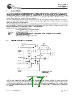
5.1.1
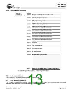
Program Memory Organization
after reset
14-bit PC
Address
0x0000
Program execution begins here after a reset
USB Bus Reset interrupt vector
128-µs timer interrupt vector
0x0002
0x0004
0x0006
0x0008
0x000A
0x000C
0x000E
0x0010
0x0012
0x0014
0x0016
0x0018
0x001A
1.024-ms timer interrupt vector
USB address A endpoint 0 interrupt vector
USB address A endpoint 1 interrupt vector
USB address A endpoint 2 interrupt vector
USB address A endpoint 3 interrupt vector
USB address A endpoint 4 interrupt vector
Reserved
DAC interrupt vector
GPIO interrupt vector
I2C interrupt vector
Program Memory begins here
0x1FDF
8 KB (-32) PROM ends here (CY7C64013, CY7C64113)
Figure 5-1. Program Memory Space with Interrupt Vector Table
5.2
8-Bit Accumulator (A)
The accumulator is the general-purpose register for the microcontroller.
5.3
8-Bit Temporary Register (X)
The “X” register is available to the firmware for temporary storage of intermediate results. The microcontroller can perform indexed
operations based on the value in X. Refer to Section 5.6.3 for additional information.
Document #: 38-08001 Rev. **
Page 13 of 48

 CYPRESS [ CYPRESS ]