FOR
FOR
CY7C63411/12/13
CY7C63511/12/13
CY7C63612/13
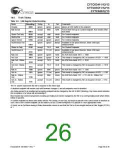
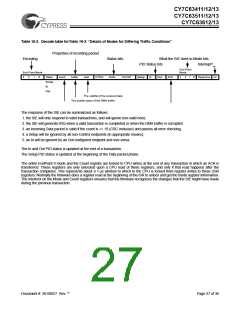
Table 16-2. Decode table forTable 16-3: “Details of Modes for Differing Traffic Conditions”
Properties of incoming packet
Encoding
Status bits
What the SIE does to Mode bits
PID Status bits Interrupt?
End Point
Mode
End Point Mode
3
2
1
0
Token
Setup
In
count
buffer
dval
DTOG
DVAL
COUNT
Setup
In
Out
ACK
3
2
1
0
Response Int
Out
The validity of the received data
The quality status of the DMA buffer
The response of the SIE can be summarized as follows:
1. the SIE will only respond to valid transactions, and will ignore non-valid ones;
2. the SIE will generate IRQ when a valid transaction is completed or when the DMA buffer is corrupted
3. an incoming Data packet is valid if the count is <= 10 (CRC inclusive) and passes all error checking;
4. a Setup will be ignored by all non-Control endpoints (in appropriate modes);
5. an In will be ignored by an Out configured endpoint and vice versa.
The In and Out PID status is updated at the end of a transaction.
The Setup PID status is updated at the beginning of the Data packet phase.
The entire EndPoint 0 mode and the Count register are locked to CPU writes at the end of any transaction in which an ACK is
transferred. These registers are only unlocked upon a CPU read of these registers, and only if that read happens after the
transaction completes. This represents about a 1-µs window to which to the CPU is locked from register writes to these USB
registers. Normally the firmware does a register read at the beginning of the ISR to unlock and get the mode register information.
The interlock on the Mode and Count registers ensures that the firmware recognizes the changes that the SIE might have made
during the previous transaction.
Document #: 38-08027 Rev. **
Page 27 of 36

 CYPRESS [ CYPRESS ]