CX82100 Home Network Processor Data Sheet
8.4
USB DMA Interface
DMAC interfaces with the USB device through addressed writes/reads that conform to
the common DMA protocol.
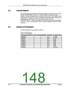
8.4.1
DMA Receive Channel
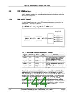
The DMA channel supporting receive OUT endpoints is illustrated in Figure 8-6. The
endpoint data is described in Table 8-3.
Figure 8-6. DMA Channel Supporting USB Receive OUT Endpoints
Endpoints
EP0_OUT
EP1_OUT
DMA Ch 12
DMA Ch 12
ARM Host
DMAC
USB Device
EP2_OUT
EP3_OUT
101545_059
Table 8-3. DMA Channel Supporting USB Receive OUT Endpoints
Endpoint
Direction
Name
DMA
Description
No.
Channel
Endpoint 0
OUT
EP0_OUT
12
USB specification Chapter 9 compliance
and other USB stack aware commands.
Maximum packet size is 64 bytes.
Endpoint 1
Endpoint 2
Endpoint 3
OUT
OUT
OUT
EP1_OUT
EP2_OUT
EP3_OUT
12
12
12
Bulk OUT data. Maximum packet size is
64 bytes.
Bulk OUT data. Maximum packet size is
64 bytes.
Bulk OUT data. Maximum packet size is
64 bytes.
Whenever the host sends a control/data packet that is forwarded by the HNP, the data is
then organized in 8-byte qword segments by the UDC Core and written to a circular
DMA RX buffer (the pointer and buffer length has been initialized for DMA Channel 12
operation by the firmware). Each forwarded packet consists of an 8-byte Status Header
followed by packet control/data payload arranged in little endian byte order. The exact
number of bytes of the received data/control packet is specified in the COUNT parameter
of the Status Header. In case of a transaction having a non-integer of qword boundary,
the last qword in the USB RX buffer segment holding that packet’s data is zero-padded in
higher order locations. Firmware also keeps track of the next packet pointer location in
the circular DMA RX buffer. The Status Header is defined in Table 8-4.
8-10
Conexant Proprietary and Confidential Information
101306C

 CONEXANT [ CONEXANT SYSTEMS, INC ]