CX82100 Home Network Processor Data Sheet
8.4.2
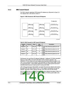
DMA Transmit Channel
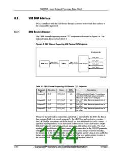
The DMA channels supporting USB transmit IN endpoints are illustrated in Figure 8-6.
The endpoint data is described in Table 8-3.
Figure 8-7. DMA Channels for USB Transmit IN Endpoints
Endpoints
EP0_IN (Ch 13)
EP1_IN (Ch 11)
EP2_IN (Ch 10)
EP3_IN (Ch 9)
DMA Ch 13
DMA Ch 11
DMA Ch 10
DMA Ch 9
DMA Ch 13
DMA Ch 11
DMA Ch 10
DMA Ch 9
ARM Host
DMAC
USB Device
101545_060
Table 8-5. DMA Channels for USB Transmit IN Endpoints
Endpoint
Direction
Name
EP0_IN
EP1_IN
EP2_IN
EP3_IN
DMA
Description
No.
Channel
Endpoint 0
Endpoint 1
Endpoint 2
Endpoint 3
IN
IN
IN
IN
13
11
10
9
Control data. Maximum packet size is 64
bytes.
Bulk IN data. Maximum packet size is 64
bytes.
Bulk IN data. Maximum packet size is 64
bytes.
Bulk IN data. Maximum packet size is 64
bytes.
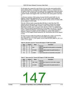
The firmware sets up all four IN endpoint (Endpoint0 – Endpoint3) TX DMA embedded
link-list circular buffers associated with DMAC DMA channels separately. The
APB/DMA I/F then obtains and sends endpoint data from these linked-list buffers to the
UDC Core in response to host requests. Each individual TX DMA packet buffer consists
of a qword Descriptor + Status header followed by 64 bytes of data payload and qword
embedded link-list pointer/counter pointed to next packet buffer.
After setting up the proper DMA buffer associated with particular endpoint and resetting
the proper EPX_IN_DMA_RESET bit in U_CTR1 register, the firmware activates the
endpoint, optionally enables endpoint interrupt, and is then ready for data transfer.
Once an endpoint data is ready, the firmware puts proper endpoint description (Table 8-6)
and data payload (up to 64 bytes) into corresponding the TX DMA packet buffer at the
current DMA pointer.
8-12
Conexant Proprietary and Confidential Information
101306C

 CONEXANT [ CONEXANT SYSTEMS, INC ]