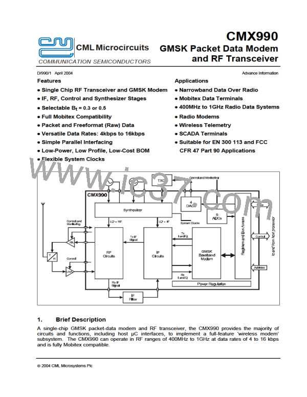
GMSK Packet Data Modem and RF Transceiver
CMX990
5.1.4.4 Mode Register
The contents of this 8-bit write only register control the basic operating modes of the modem:
Mode Register
$03
Write
7
6
5
4
3
2
1
0
Bit:
IRQ
Enable
En PLL
Lock IRQ
Enable DQ
IRQ
Enable
Main ADC
Enable
Main DAC
INVBit
TxRxN
SCREn
Mode Register B7: IRQ Enable - IRQN Output Enable
When this bit is set to ‘1’ the IRQN chip output pin is pulled low (to V ) whenever the IRQ bit of
ss
the Status Register is a ‘1’.
Mode Register B6: INVBIT - Invert Bits
This bit controls inversion of transmitted and received data. This allows for frequency inversions
in the RF chain and has the effect of swapping I and Q paths in both transmitter and receiver.
Mode Register B5: TXRXN - Tx/Rx Mode
Setting this bit to ‘1’ puts the modem into Transmit mode, clearing it to ‘0’ puts the modem into
Receive mode. When changing from Rx to Tx there must be a 2-bit pause before setting a new
task to allow the filter to stabilise. (See also Baseband Enable bit).
Note that changing between receive and transmit modes will cancel any current task. Note also
that this bit does not enable Tx or Rx sections of the CMX990 which must be enabled by
separate control bits.
Mode Register B4: SCREN - Scramble Enable
The scrambler only takes effect during the transmission or reception of a Mobitex Data Block,
Short Data Block and during a TSO task. Setting this bit to ‘1’ enables scrambling, clearing it to
‘0’ disables scrambling.
The scrambler is only operative, if enabled by this control bit, during TSO, RDB, RSD, TSD or
TDB, it is held in a reset state at all other times.
This bit should not be changed while the modem is decoding or transmitting a Mobitex Data
Block.
Mode Register B3: En PLL Lock IRQ - Enable Phase Lock Loop lost IRQ
Setting this bit to ‘1’ causes the IRQ bit of the Status 1 Register to be set to ‘1’ whenever The PLL
Lock lost bit is set to 1. (The Phase Lock lost bit of Status 2 Register will also be set to ‘1’ at the
same time.)
Mode Register B2: Enable DQ IRQ - Enable Data Quality IRQ
In receive mode, setting this bit to ‘1’ causes the IRQ bit of the Status 1 Register to be set to ‘1’
whenever a new Data Quality reading is ready. (The DQRDY bit of the Status 1 Register will
also be set to ‘1’ at the same time.)
In transmit mode this bit has no effect.
Mode Register B1 - 0: Enable Main ADC / Enable Main DAC
When the respective bit is set to ‘1’ the main ADC and DAC are enabled, power may be saved by
setting these bits to ‘0’ when the ADC or DAC are not needed. Bit ‘0’ would normally only be set
to ‘1’ when bit 5 is set to ‘1’. Bit ‘1’ would normally only be set to ‘1’ when bit 5 is set to ‘0’.
ã 2004 CML Microsystems Plc
33
D/990/1

 CMLMICRO [ CML MICROCIRCUITS ]