GMSK Packet Data Modem and RF Transceiver
CMX990
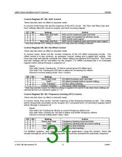
The bit is cleared to ‘0’ by writing a task other than NULL, RESET or TSO to the Command
Register.
Note: When the modem is in transmit mode and the Interleave Buffer is empty, a mid-level
voltage (VBIAS) will be applied to the Tx low pass filter.
In receive mode this bit will be ‘0’.
Status 1 Register, B4: DIBOVF - De-Interleave Buffer Overflow
In receive mode this bit will be set to ‘1’ (also setting the IRQ bit) when a task is written to the
Command Register too late to allow continuous reception.
The bit is cleared to ‘0’ by reading the Status 1 Register or by writing a RESET task to the
Command Register or by changing the Enable Baseband or TXRXN bits of the Mode Register.
In transmit mode this bit will be ‘0’.
Status 1 Register, B3: CRCFEC - CRC or FEC Error
In receive mode this bit will be updated at the end of a Mobitex Data Block task, after checking
the CRC, and at the end of receiving Frame Head control bytes, after checking the FEC. A ‘0’
indicates that the CRC was received correctly or the FEC did not find uncorrectable errors, a ‘1’
indicates that errors are present.
The bit is only cleared to ‘0’ by a RESET task or by changing the Enable Baseband or TXRXN
bits of the Mode Register.
In transmit mode this bit will be ‘0’.
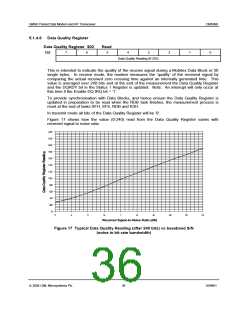
Status 1 Register, B2: DQRDY - Data Quality Reading Ready
In receive mode, this bit is set to ‘1’ whenever a Data Quality reading has been completed.
The bit is cleared to '0' after reading the Data Quality Register.
Immediately after a RESET task, or a change in the Enable Baseband or TXRXN bits to ‘0’, the
DQRDY bit may be set and generate an interrupt. The value in the Data Quality Register will
not be valid in this case.
Status 1 Register, B1: MOBAN - Mobile or Base Bit Sync Received
In receive mode this bit is updated at the end of the SFS and SFH tasks. This bit is set to ‘1’
whenever the 3 bits immediately preceding a detected Frame sync are ‘011’ (received left to
right), with up to any one bit in error. The bit is set to ‘0’ if the bit pattern is ‘100’, again with up
to any one bit in error. Thus, if this bit is set to ‘1’ then the received message is likely to have
originated from a Mobile and if it is set to ‘0’ from a Base Station.
In transmit mode this bit is a logic ‘0’.
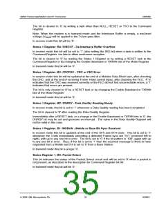
Status Register 1, B0: Packet Detect
This bit indicates the status of the Packet Detect circuit and will be set to '0' when a packet is
not present, as described in the description for Command Register bit B4.
In transmit mode this bit will be ‘0’.
ã 2004 CML Microsystems Plc
35
D/990/1

 CMLMICRO [ CML MICROCIRCUITS ]