CS8900A
Crystal LAN™ Ethernet Controller
at least four frames in a row with negative po-
larity after the EOF, the receive pair is consid-
ered reversed. Any data received before the
correction of the reversal is ignored.
AUI
Collision
CL+
CL-
AUICol (to MAC)
AUIR X
Detect
-
+
3.11.6 Collision Detection
If half-duplex operation is selected (Register
19, Bit E, FDX), the CS8900A detects a
10BASE-T collision whenever the receiver and
transmitter are active simultaneously. When a
collision is present, the Collision Detection cir-
cuit informs the MAC by asserting the internal
Collision signal (see Section 3.9 on page 29
for collision handling).
DI+
DI-
AUISQL
AUITX
ENDEC
-
+
DO+
D O -
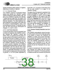
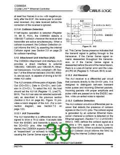
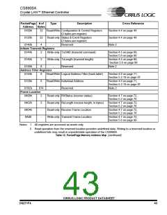
Figure 15. AUI
ed. This Carrier Sense presence indicates that
the transmit signal is getting through to the
transceiver. If the Carrier Sense signal re-
mains deasserted throughout the transmis-
sion, or if the Carrier Sense signal is
deasserted before the end of the transmission,
there is a Loss-of-Carrier error and the Loss-
of-CRS bit (Register 8, TxEvent, Bit 6) is set.
3.12 Attachment Unit Interface (AUI)
The CS8900A Attachment Unit Interface (AUI)
provides a direct interface to external
10BASE2, 10BASE5, and 10BASE-FL Ether-
net transceivers. It is fully compliant with Sec-
tion 7 of the Ethernet standard (ISO/IEC 8802-
3), and as such, is capable of driving a full 50-
meter AUI cable.
3.12.2 AUI Receiver
The AUI receiver is a differential pair circuit
that connects directly to the DI+/DI- pins. It is
designed to distinguish between transient
noise pulses and incoming Ethernet packets.
Incoming packets with proper amplitude and
pulse width are passed on to the ENDEC sec-
tion, while unwanted noise is rejected.
The AUI consists of three pairs of signals: Data
Out (DO+/DO-), Data In (DI+/DI-), and Colli-
sion In (CI+/CI-). To select the AUI, the host
should set the AUI bit (Register 13, LineCTL,
Bit 8). The AUI can also be selected automati-
cally as described in the previous section
(Section 3.10.4 on page 36). Figure 15 pro-
vides a block diagram of the AUI. (For a con-
nection diagram, see Section 7.6 on
page 122).
3.12.3 Collision Detection
The AUI collision circuit is a differential pair re-
ceiver that detects the presence of collision
signals on the CI+/CI- pins. The collision signal
is generated by an external Ethernet trans-
ceiver whenever a collision is detected on the
Ethernet segment. (Section 7.3.1.2 of ISO/IEC
8802-3, 1993, defines the collision signal as a
10 MHz ± 15% signal with a duty cycle no
worse than 60/40). When a collision is present,
the AUI Collision circuit informs the MAC by
asserting the internal Collision signal.
3.12.1 AUI Transmitter
The AUI transmitter is a differential driver de-
signed to drive a 78 Ω cable. It accepts data
from the ENDEC and transmits it directly on
the DO+/DO- pins. After transmission has
started, the CS8900A expects to see the pack-
et “looped-back” (or echoed) to the receiver,
causing the Carrier Sense signal to be assert-
CIRRUS LOGIC PRODUCT DATASHEET
DS271F4
39

 CIRRUS [ CIRRUS LOGIC ]