CS8900A
Crystal LAN™ Ethernet Controller
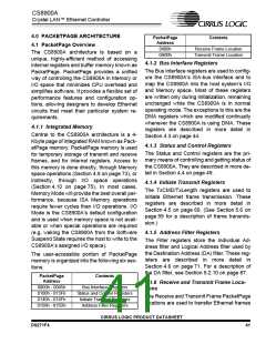
LinkO K
(to M AC)
10BASE-T Transceiver
Link Pulse
Detector
RX Squelch
RXSQL
R X
RXD -
RXD+
R X
RX Filters
Com parator
ENDEC
TXD-
TXD+
TX
TX Pre-
Distortion
TX Filters
TX Drivers
Filter Tuning
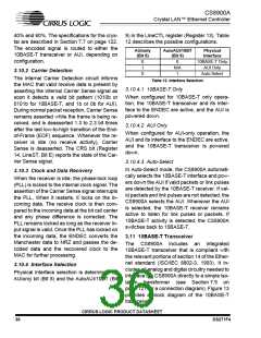
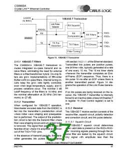
Figure 13. 10BASE-T Transceiver
3.11.1 10BASE-T Filters
with section 14.2.1.1. of the Ethernet standard.
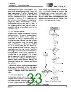
Transmitted link pulses are positive pulses,
one bit time wide, typically generated at a rate
of one every 16 ms. The 16 ms timer starts
whenever the transmitter completes an End-
of-Frame (EOF) sequence. Thus, there is a
link pulse 16 ms after an EOF unless there is
another transmitted packet. Figure 14 dia-
grams the operation of the Link Pulse Genera-
tor.
The CS8900A’s 10BASE-T transceiver in-
cludes integrated low-pass transmit and re-
ceive filters, eliminating the need for external
filters or a filter/transformer hybrid. On-chip fil-
ters are gm/c implementations of fifth-order
Butterworth low-pass filters. Internal tuning cir-
cuits keep the gm/c ratio tightly controlled,
even when large temperature, supply, and IC
process variations occur. The nominal 3 dB
cutoff frequency of the filters is 16 MHz, and
the nominal attenuation at 30 MHz (3rd har-
monic) is -27 dB.
If no link pulses are being received on the re-
ceiver, the 10BASE-T transmitter is internally
forced to an inactive state unless bit DisableLT
in register 19 (Test Control register) is set to
one.
3.11.2 Transmitter
When configured for 10BASE-T operation,
Manchester encoded data from the ENDEC is
fed into the transmitter’s predistortion circuit
where initial wave shaping and preequaliza-
tion is performed. The output of the predistor-
tion circuit is fed into the transmit filter where
final wave shaping occurs and unwanted noise
is removed. The signal then passes to the dif-
ferential driver where it is amplified and driven
out of the TXD+/TXD- pins.
3.11.3 Receiver
The 10BASE-T receive section consists of the
receive filter, squelch circuit, polarity detection
and correction circuit, and link pulse detector.
3.11.3.1 Squelch Circuit
The 10BASE-T squelch circuit determines
when valid data is present on the RXD+/RXD-
pair. Incoming signals passing through the re-
ceive filter are tested by the squelch circuit.
Any signal with amplitude less than the
In the absence of transmit packets, the trans-
mitter generates link pulses in accordance
CIRRUS LOGIC PRODUCT DATASHEET
DS271F4
37

 CIRRUS [ CIRRUS LOGIC ]