CS8900A
Crystal LAN™ Ethernet Controller
40% and 60%. The specifications for the crys-
tal are described in Section 7.7 on page 122.
The encoded signal is routed to either the
10BASE-T transceiver or AUI, depending on
configuration.
9) in the LineCTL register (Register 13). Table
12 describes the possible configurations.
AUIonly
(Bit 8)
AutoAUI/10BT
(Bit 9)
Physical
Interface
0
1
0
0
N/A
1
10BASE-T Only
AUI Only
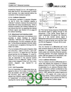
3.10.2 Carrier Detection
Auto-Select
The internal Carrier Detection circuit informs
the MAC that valid receive data is present by
asserting the internal Carrier Sense signal as
soon it detects a valid bit pattern (1010b or
0101b for 10BASE-T, and 1b or 0b for AUI).
During normal packet reception, Carrier Sense
remains asserted while the frame is being re-
ceived, and is deasserted 1.3 to 2.3 bit times
after the last low-to-high transition of the End-
of-Frame (EOF) sequence. Whenever the re-
ceiver is idle (no receive activity), Carrier
Sense is deasserted. The CRS bit (Register
14, LineST, Bit E) reports the state of the Car-
rier Sense signal.
Table 12. Interface Selection
3.10.4.1 10BASE-T Only
When configured for 10BASE-T only opera-
tion, the 10BASE-T transceiver and its inter-
face to the ENDEC are active, and the AUI is
powered down.
3.10.4.2 AUI Only
When configured for AUI-only operation, the
AUI and its interface to the ENDEC are active,
and the 10BASE-T transceiver is powered
down.
3.10.4.3 Auto-Select
In Auto-Select mode, the CS8900A automati-
cally selects the 10BASE-T interface and pow-
ers down the AUI if valid packets or link pulses
are detected by the 10BASE-T receiver. If val-
id packets and link pulses are not detected, the
CS8900A selects the AUI. Whenever the AUI
is selected, the 10BASE-T receiver remains
active to listen for link pulses or packets. If
10BASE-T activity is detected, the CS8900A
switches back to 10BASE-T.
3.10.3 Clock and Data Recovery
When the receiver is idle, the phase-lock loop
(PLL) is locked to the internal clock signal. The
assertion of the Carrier Sense signal interrupts
the PLL. When it restarts, it locks on the in-
coming data. The receive clock is then com-
pared to the incoming data at the bit cell center
and any phase difference is corrected. The
PLL remains locked as long as the receiver in-
put signal is valid. Once the PLL has locked on
the incoming data, the ENDEC converts the
Manchester data to NRZ and passes the de-
coded data and the recovered clock to the
MAC for further processing.
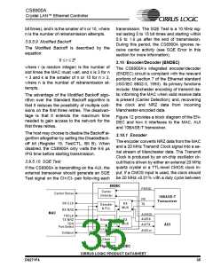
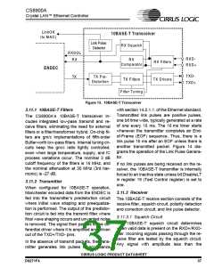
3.11 10BASE-T Transceiver
The CS8900A includes an integrated
10BASE-T transceiver that is compliant with
the relevant portions of section 14 of the Ether-
net standard (ISO/IEC 8802-3, 1993). It in-
cludes all analog and digital circuitry needed to
interface the CS8900A directly to a simple iso-
lation transformer (see Section 7.5 on
page 121 for a connection diagram). Figure 13
provides a block diagram of the 10BASE-T
transceiver.
3.10.4 Interface Selection
Physical interface selection is determined by
AUIonly bit (Bit 8) and the AutoAUI/10BT (Bit
CIRRUS LOGIC PRODUCT DATASHEET
36
DS271F4

 CIRRUS [ CIRRUS LOGIC ]