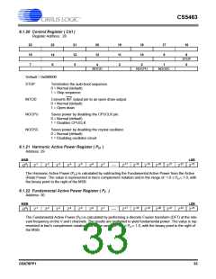
CS5463
VHPF
Enables the High-pass Filter on the voltage channel.
0 = High-pass filter disabled (default)
1 = High-pass filter enabled
Note: When either IHPF or VHPF are enabled, but not both, an all pass filter is applied to the
opposite channel for phase-matching.
IIR
Enables the IIR compensation filters.
0 = IIR compensation filters enabled (default)
1 = IIR compensation filters disabled
E3MODE1:0
E3 Output Mode
00 = Reactive Power (default)
01 = PFMON
10 = Voltage sign
11 = Apparent Power
POS
AFC
Positive Energy Only. Negative energy pulses on E1 are suppressed. However, it will NOT sup-
press negative P register results.
Enables automatic line frequency measurement and sets the frequency of the local sine/cosine
generator used in fundamental/harmonic measurements. When AFC is enabled, the Epsilon
register will be updated periodically.
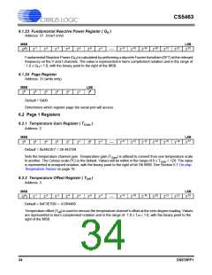
6.1.14 Temperature Register ( T )
Address: 19
MSB
LSB
7
6
5
4
3
2
1
0
-10
-11
-12
-13
-14
-15
-16
.....
-(2 )
2
2
2
2
2
2
2
2
2
2
2
2
2
2
T contains measurements from the on-chip temperature sensor. Measurements are performed during continu-
ous conversions, with the default the Celsius scale (oC). The value is represented in two's complement notation
and in the range of -128.0 ≤ T < 128.0, with the binary point to the right of the eighth MSB.
6.1.15 Average and Instantaneous Reactive Power Register ( QAVG , Q )
Address: 20 (Average Reactive Power) and 21 (Instantaneous Reactive Power)
MSB
LSB
0
-1
-2
-3
-4
-5
-6
-7
-17
-18
-19
-20
-21
-22
-23
.....
-(2 )
2
2
2
2
2
2
2
2
2
2
2
2
2
2
The Instantaneous Reactive Power (Q) is the product of the voltage, shifted 90 degrees, and the current. The
Average Reactive Power (Q ) is Q averaged over N samples. The results are signed values with. The value
AVG
is represented in two's complement notation and in the range of -1.0 < Q, Q
right of the MSB.
< 1.0, with the binary point to the
AVG
6.1.16 Peak Current and Peak Voltage Register ( Ipeak , Vpeak
)
Address: 22 (Peak Currect) and 23 (Peak Voltage)
MSB
LSB
0
-1
-2
-3
-4
-5
-6
-7
-17
-18
-19
-20
-21
-22
-23
.....
-(2 )
2
2
2
2
2
2
2
2
2
2
2
2
2
2
The Peak Current (I
) and Peak Voltage (V
) registers contain the instantaneous current and voltage with
peak
peak
the greatest magnitude detected during the last computation cycle. The value is represented in two's comple-
ment notation and in the range of -1.0 ≤ I , V < 1.0, with the binary point to the right of the MSB.
peak
peak
DS678PP1
31

 CIRRUS [ CIRRUS LOGIC ]