CS49300 Family DSP
to send a 7-bit address along with a read/write bit at
the start of any serial transaction. By default,
address checking is disabled in the CS493XX. See
below for how to enable address checking.
11. HARDWARE CONFIGURATION
After download or soft reset, and before
kickstarting the application (please see the Audio
Manager in the Application Messaging Section of
any application code user’s guide for more
information on kickstarting), the host has the
option of changing the default hardware
configuration. Hardware configuration messages
are used to physically reconfigure the hardware of
The following 4-word hex message configures the
address checking circuitry of the CS493XX: It
should be noted that this will allow the host to
enable address checking and change the address of
the device. If address checking disabled is
the audio decoder, as in enabling or disabling acceptable, then these messages do not need to be
address checking for the serial communication
port. Hardware configuration messages are also
used to initialize the data type (i.e., PCM or
sent.
0x800252
0x00FFFF
0x800152
0xHH0000
2
compressed) and format (e.g., I S, Left Justified,
Parallel, or Serial Bursty) for digital data inputs, as
well as the data format and clocking options for the
digital output port.
In the last word the following bits should replace
HH:
In general, the hardware configuration can only be
changed immediately after download or after soft
reset. However, some applications provide the
capability to change the input ports without
Bits 23:17 - New Address to use for checking (if
enabling address checking)
affecting other hardware configurations after Bit 16 - 1 = Address checking on
sending a special Application Restart message
(please see the Audio Manager in any Application
Code User’s Guide to determine whether the
Application Restart message is supported).
0 = Address checking off
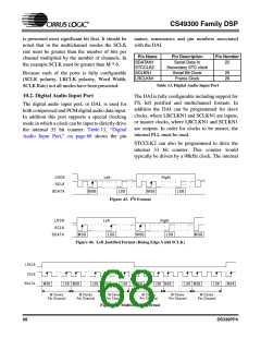
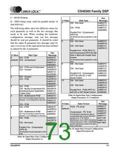
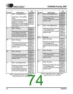
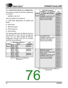
11.2. Input Data Hardware Configuration
2
Both data format (I S, Left Justified, Parallel, or
Serial Bursty) and data type (compressed or PCM)
are required to fully define the input port’s
hardware configuration. The DAI and the CDI are
configured by the same group of messages since
their configurations are interrelated. The naming
convention of the input hardware configuration is
as follows:
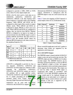
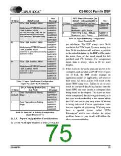
Serial digital audio data bit placement and sample
alignment is fully configurable in the CS493XX
including left justified, right justified, delay bits or
no delay bits, variable sample word sizes, variable
output channel count, and programmable output
channel pin assignments and clock edge polarity to
integrate with most digital audio interfaces. If a
mode is needed which is not presented, please
consult your sales representative as to its
availability.
INPUT A B C D
where A, B, C and D are the parameters used to
fully define the input port. The parameters are
defined as follows:
11.1. Address Checking
A - Data Type
When using one of the serial communication
2
modes, I C or SPI, as discussed in Section 6.1, B - Data Format (This is a don’t care for parallel
“Serial Communication” on page 33, it is necessary
modes of data delivery)
72
DS339PP4

 CIRRUS [ CIRRUS LOGIC ]