CS49300 Family DSP
Hex
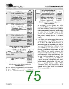
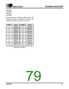
FIFO Size & Blocksize (no
B Value
8
Data Format
PCM - Left Justified 24-bit
Message
0x800217
0x8080FF
default - only applicable to
parallel delivery modes)
Compressed FIFO B Size -
6kbyte
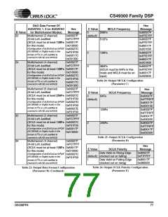
Hex
D Value
1
Message
0x800014
0x280D00
Multichannel PCM (6 Channel) 0x80021A
- Left Justified 20-bit
0x8080FF
0x800117
0x003CC0
0x80011A
0x0018C0
0x800217
0x8080FF
Blocksize - up to 2kbyte
PCM FIFO C Size - 6kbyte
Blocksize - up to 2kbyte
(for Post-Processing Codes that can
accept 6 channels on one line like
THX Surround EX application code)
2
0x800014
0x820300
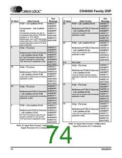
Table 21. Input FIFO Setup Configuration
(Input Parameter D)
82
84
PCM - Left Justified 24-bit
per sub-frame. The DSP always uses 24-bit
resolution for PCM input. Systems having less
than 24-bit resolution will not have a problem
as the extra bits taken by the DSP will be under
the noise floor of the input signal for left
Multichannel PCM (2 Channel) 0x80021A
- Left Justified 20-bit
(used only by special post-processing
application codes)
0x8080FF
0x800117
0x0014C0
0x80011A
0x0018C0
0x800217
0x8080FF
2
justified and I S formats. For compressed
PCM - Left Justified 24-bit
input, data is always taken in 16 bit word
lengths.
Multichannel PCM (4 Channel) 0x80021A
- Left Justified 20-bit
(used only by special post-processing
application codes)
0x8080FF
0x800117
0x0028C0
0x80011A
0x0018C0
2) If the clocks to the audio ports are known to be
corrupted, such as when a S/PDIF receiver goes
out of lock, the DSP should undergo an
application restart (if applicable), soft reset or
hard reset. All three actions will result in the
input FIFO being reset. Failure to do so may
result in corrupted data being latched into the
input FIFO and may result in corrupted data
being heard on the outputs. This is not an issue
when compressed data is being delivered, as it
has sync words embedded in the stream which
the DSP can lock to, but only when PCM data
is being delivered. Certain application codes
that are capable of processing PCM may now
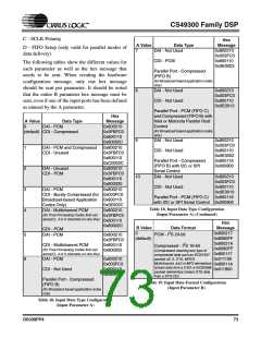
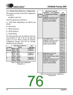
Table 19. Input Data Format Configuration
(Input Parameter B) (Continued)
SCLK Polarity (Both CDI &
DAI Port)
Data Clocked in on Rising
Hex
C Value
0
Message
0x800217
0xFFFFDF
0x80021A
0xFFFFDF
0x800117
0x000020
0x80011A
0x000020
(default) Edge
1
Data Clocked in on Falling
Edge
have
a
special feature called “PCM
Table 20. Input SCLK Polarity Configuration
(Input Parameter C)
Robustness” which does alleviate the above
problem, however you should still follow the
above recommendation.
11.2.1. Input Configuration Considerations
1) 24-bit PCM input requires at least 24 SCLKS
DS339PP4
75

 CIRRUS [ CIRRUS LOGIC ]