CS49300 Family DSP
is presented most significant bit first. It should be
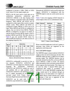
names, mnemonics and pin numbers associated
noted that in the multichannel modes the SCLK with the DAI.
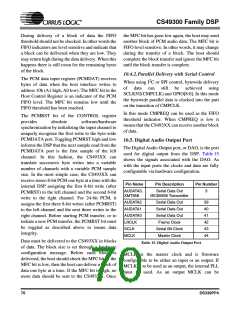
rate must be greater than the number of bits per
Pin Name
Pin Description
Serial Data In
Secondary STC clock
Serial Bit Clock
Frame Clock
Pin Number
channel multiplied by the number of channels. In
SDATAN1
the example SCLK must be greater than M * 6.
STCCLK2
22
SCLKN1
LRCLKN1
25
26
Because each of the ports is fully configurable
(SCLK polarity, LRCLK polarity, Word Width,
SCLK Rate) not all modes have been presented.
Table 13. Digital Audio Input Port
10.2. Digital Audio Input Port
The DAI is fully configurable including support for
I2S, left justified and multichannel formats. In
addition the DAI can be programmed for slave
clocks, where LRCLKN1 and SCLKN1 are inputs,
or master clocks, where LRCLKN1 and SCLKN1
are outputs. In order for clocks to be master, the
internal PLL must be used.
The digital audio input port, or DAI, is used for
both compressed and PCM digital audio data input.
In addition this port supports a special clocking
mode in which a clock can be input to directly drive
the internal 33 bit counter. Table 13, “Digital
Audio Input Port,” on page 68 shows the pin
STCCLK2 can also be programmed to drive the
internal 33 bit counter. This counter would
typically be driven by a 90kHz clock. The internal
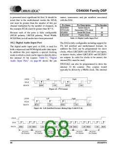
LR C K
SC LK
Left
Right
SD ATA
M SB
LSB
M SB
LS B
Figure 43. I2S Format
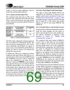
LRCK
SC LK
Left
Right
SDATA
M SB
LSB
M SB
LSB
M SB
Figure 44. Left Justified Format (Rising Edge Valid SCLK)
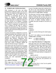
LRCLK
SCLK
SDATA
M SB
LSB M SB
LSB M SB
LSB
M SB
LSB M SB
LSB M SB
LSB
MS B
M Clocks
Per Channel
M Clocks
Per Channel
M Clocks
Per Channel
M Clocks
Per Channel
M Clocks
Per Channel
M Clocks
Per Channel
Figure 45. Multichannel Format
68
DS339PP4

 CIRRUS [ CIRRUS LOGIC ]