CS49300 Family DSP
configured to provide a 128Fs, 256Fs or 512Fs
clock, where Fs is the output sample rate.
Alternatively AUDATA3 can be used for dual zone
support. AUDATA3 is multiplexed with the
XMT958 output so only one can be used at any one
time.
SCLK is the bit clock used to clock data out on
AUDATA0, AUDATA1, AUDATA2 and
AUDATA3. LRCLK is the data framing clock
whose frequency is typically equal to the sampling
frequency. Both LRCLK and SCLK can be
configured as either inputs (Slave mode) or outputs
(Master mode). When LRCLK and SCLK are
configured as inputs, MCLK is a don’t care as an
input. When LRCLK and SCLK are configured as
outputs, they are derived from MCLK. Whether
MCLK is configured as an input or an output, an
internal divider from the MCLK signal is used to
produce LRCLK and SCLK. The ratios shown in
Table 16 give the possible SCLK values for
different MCLK frequencies (all values in terms of
the sampling frequency, Fs).
Table 17 shows the mapping of DAO channels to
actual outputs when not in a multichannel mode.
DAO_Channel
Subframe
Left
Signal
0
1
2
3
4
5
6
7
AUDATA0
AUDATA0
AUDATA1
AUDATA1
AUDATA2
AUDATA2
AUDATA3
AUDATA3
Right
Left
Right
Left
Right
Left
Right
Table 17. Output Channel Mapping
SCLK (Fs)
MCLK
Please consult the application code user’s guides to
determine what modes are supported by the
application code being used.
(Fs)
32
48
64
128
256
512
128
X
X
384**
256
X
X
X
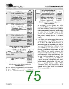
10.5.1.IEC60958 Output
X
X
X
X
X
X
The XMT958 output is shared with the AUDATA3
output so only one can be used at any one time. The
XMT958 output provides a CMOS level bi phase
encoded output. The XMT958 function can be
internally clocked from the PLL or from an MCLK
input if MCLK is 256Fs or 512Fs. All channel
status information can be used when using software
which supports this functionality. This output can
be used for either 2 channel PCM output or
compressed data output in accordance with
IEC61937. To be fully IEC60958 compliant this
output would need to be buffered through an
RS422 device or an optocoupler as its outputs are
only CMOS. Please consult software user’s guide
to determine if this pin is supported by the
download code being used.
512
X
X
X
** For MCLK as an input only
Table 16. MCLK/SCLK Master Mode Ratios
AUDAT0 is configurable to provide six, four, or
two channels. AUDATA1, AUDATA2 and
AUDATA3 can both output two channels of data.
Typically
the
AUDATA0,
AUDATA1,
AUDATA2 and AUDATA3 outputs are used in
left justified, I2S or right justified modes.
AUDATA0, AUDATA1 and AUDATA2 are used
for 5.1 output, presenting all six channels of
surround sound (Left, Center, Right, Left
Surround, Right Surround and Subwoofer).
AUDATA3 can be used with AUDATA0,
AUDATA1 and AUDATA2 to support 7.1 output.
DS339PP4
71

 CIRRUS [ CIRRUS LOGIC ]