CS2000-OTP
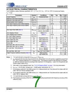
AC ELECTRICAL CHARACTERISTICS
Test Conditions (unless otherwise specified): VD = 3.1 V to 3.5 V; T = -10°C to +70°C (Commercial Grade);
A
C = 15 pF.
L
Parameters
Symbol
fXTAL
Conditions
Min
Typ
Max Units
Crystal Frequency
Fundamental Mode
8
8
-
-
-
50
75
MHz
MHz
%
Reference Clock Input Frequency
fREF_CLK
DREF_CLK
fSYS_CLK
fCLK_IN
Reference Clock Input Duty Cycle
45
55
Internal System Clock Frequency
8
18.75
30
MHz
MHz
Clock Input Frequency (Auto R-Mod Disabled)
Clock Input Frequency (Auto R-mod Enabled)
50 Hz
-
fCLK_IN
Auto R Modifier = 1
Auto R Modifier = 0.5
Auto R Modifier = 0.25
4
72
168
-
-
-
59
138
256
kHz
kHz
kHz
Clock Input Pulse Width (Note 3)
pwCLK_IN
fCLK_IN < fSYS_CLK/96
fCLK_IN > fSYS_CLK/96
2
10
-
-
-
-
UI
ns
Clock Skipping Timeout
tCS
fCLK_SKIP
fCLK_OUT
tOD
(Notes 4, 5)
(Note 5)
20
-
-
-
80
75
52
3.0
3.0
150
-
ms
kHz
Clock Skipping Input Frequency
PLL Clock Output Frequency
PLL Clock Output Duty Cycle
Clock Output Rise Time
50 Hz
6
48
-
-
MHz
%
Measured at VD/2
20% to 80% of VD
80% to 20% of VD
(Note 6)
50
1.7
1.7
70
50
175
tOR
ns
Clock Output Fall Time
tOF
-
ns
Period Jitter
tJIT
-
ps rms
ps rms
ps rms
Base Band Jitter (100 Hz to 40 kHz)
Wide Band JItter (100 Hz Corner)
PLL Lock Time - CLK_IN (Note 9)
(Notes 6, 7)
-
(Notes 6, 8)
-
-
tLC
fCLK_IN < 200 kHz
fCLK_IN > 200 kHz
-
-
100
1
200
3
UI
ms
PLL Lock Time - REF_CLK
tLR
ferr
fREF_CLK = 8 to 75 MHz
-
1
2
ms
Output Frequency Synthesis Resolution (Note 10)
High Resolution
High Multiplication
0
0
-
-
±0.5
±112
ppm
ppm
Notes: 3. 1 UI (unit interval) corresponds to t
or 1/f
.
SYS_CLK
SYS_CLK
4.
t
represents the time from the removal of CLK_IN by which CLK_IN must be re-applied to ensure that
CS
PLL_OUT continues while the PLL re-acquires lock. This timeout is based on the internal VCO frequen-
cy, with the minimum timeout occurring at the maximum VCO frequency. Lower VCO frequencies will
result in larger values of t
.
CS
5. Only valid in clock skipping mode; See “CLK_IN Skipping Mode” on page 11 for more information.
6. fCLK_OUT = 24.576 MHz; Sample size = 10,000 points; AuxOutSrc[1:0] = 11.
7. In accordance with AES-12id-2006 section 3.4.2. Measurements are Time Interval Error taken with 3rd
order 100 Hz to 40 kHz bandpass filter.
8. In accordance with AES-12id-2006 section 3.4.1. Measurements are Time Interval Error taken with 3rd
order 100 Hz Highpass filter.
9. 1 UI (unit interval) corresponds to t
or 1/f
.
CLK_IN
CLK_IN
10. The frequency accuracy of the PLL clock output is directly proportional to the frequency accuracy of the
reference clock.
DS758PP1
7

 CIRRUS [ CIRRUS LOGIC ]