SinglePhaseEnergyMeterIC
with Integrated Oscillator
BL6506
7) Power Supply Monitor
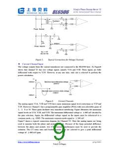
BL6506 has the on-chip Power Supply monitoring The BL6506 will remain in a reset
condition until the supply voltage on VDD reaches 4 V. If the supply falls below 4 V, the BL6506
will also be reset and no pulses will be issued on F1, F2 and CF.
ꢀ TIMING CHARACTERISTIC
(VDD=5V, GND=0V, On-Chip Reference, Integrated Oscillator, Temperature range: -20~+70°C)
Parameter
Value
Comments
t1
144ms
F1 and F2 pulse-width (Logic Low). When the power is low,
the t1 is equal to 144ms; when the power is high, and the
output period falls below 280ms, t1 equals to half of the
output period.
t2
t3
t4
t5
F1 or F2 output pulse period.
½ t2
Time between F1 falling edge and F2 falling edge.
CF Pulse Period. See Transfer Function section.
CF pulse-width (Logic high). When the power is low, the t5
is equal to 71ms; when the power is high, and the output
period falls below 140ms, t5 equals to half of the output
period.
71ms
t6
CLKIN/4 Minimum Time Between F1 and F2.
Notes:
1) CF is not synchronous to F1 or F2 frequency outputs.
2) Sample tested during initial release and after any redesign or process change that may affect this
parameter.
ꢀ THEORY OF OPERATION
ꢀ
Principle of Energy Measure
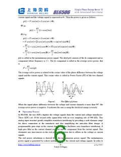
In energy measure, the power information varying with time is calculated by a direct
multiplication of the voltage signal and the current signal. Assume that the current signal and the
voltage signal are cosine functions; V and I are the peak values of the voltage signal and the
current signal; ωis the angle frequency of the input signals; the phase difference between the
http://www.belling.com.cn
- 5 -
3/15/2007
Total 14 Pages

 BELLING [ BELLING ]