SinglePhaseEnergyMeterIC
with Integrated Oscillator
BL6506
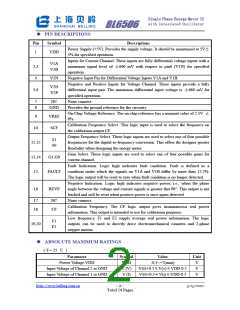
ꢀ PIN DESCRIPTIONS
Pin
Symbol
Descriptions
Power Supply (+5V). Provides the supply voltage. It should be maintained at 5V±
5% for specified operation.
1
VDD
Inputs for Current Channel. These inputs are fully differential voltage inputs with a
maximum signal level of ±660 mV with respect to pin6 (V1N) for specified
operation.
V1A
V1B
2,3
4
V1N
Negative Input Pin for Differential Voltage Inputs V1A and V1B.
Negative and Positive Inputs for Voltage Channel. These inputs provide a fully
differential input pair. The maximum differential input voltage is ±660 mV for
specified operation.
V2N
V2P
5,6
7
8
NC
None connect.
GND
Provides the ground reference for the circuitry.
On-Chip Voltage Reference. The on-chip reference has a nominal value of 2.5V ±
8%.
9
VREF
SCF
Calibration Frequency Select. This logic input is used to select the frequency on
the calibration output CF.
10
Output Frequency Select. These logic inputs are used to select one of four possible
frequencies for the digital-to-frequency conversion. This offers the designer greater
flexibility when designing the energy meter.
S1
S0
11,12
13,14
15
Gain Select. These logic inputs are used to select one of four possible gains for
current channel.
G1,G0
Fault Indication. Logic high indicates fault condition. Fault is defined as a
condition under which the signals on V1A and V1B differ by more than 12.5%.
The logic output will be reset to zero when fault condition is no longer detected.
Negative Indication. Logic high indicates negative power, i.e., when the phase
angle between the voltage and current signals is greater that 90°. This output is not
latched and will be reset when positive power is once again detected.
None connect.
FAULT
16
REVP
17
18
NC
CF
Calibration Frequency. The CF logic output gives instantaneous real power
information. This output is intended to use for calibration purposes.
Low frequency. F1 and F2 supply average real power information. The logic
outputs can be used to directly drive electromechanical counters and 2-phase
stepper motors.
F1
F2
19,20
ꢀ ABSOLUTE MAXIMUM RATINGS
( T = 25 ℃ )
Parameter
Symbol
Value
Unit
V
Power Voltage VDD
VDD
V (V)
V (I)
-0.3~+7(max)
Input Voltage of Channel 2 to GND
Input Voltage of Channel 1 to GND
VSS+0.5≤V(v)≤VDD-0.5
VSS+0.5≤V(i)≤VDD-0.5
V
V
http://www.belling.com.cn
- 2 -
Total 14 Pages
3/15/2007

 BELLING [ BELLING ]