SinglePhaseEnergyMeterIC
with Integrated Oscillator
BL6506
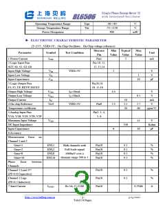
8 Positive and Negative
Real Power Error (%)
ENP
Pin18
0.3
%
Vv=±110mV,
V(I)=2mV, cosϕ=1
Vv=±110mV,
V(I)=2mV, cosϕ=-1
9 Gain Error
Gain error
Pin18
Pin18
%
%
±5
10 Gain Error Match
0.2
1
ꢀ
TERMINOLOGY
1) Measurement Error
The error associated with the energy measurement made by the BL6506 is defined by the
following formula:
Energy Re gisteredby the BL6506 −True Energy
Pencebtage Error =
×100%
True Energy
2) Nonlinear Error
The Nonlinear Error is defined by the following formula:
eNL%=[(Error at X-Error at Ib) / (1+Error at Ib )]*100%
When V(v)= ±110mV, cosϕ=1, over the arrange of 5%Ib to 800%Ib, the nonlinear error should be
less than 0.1%.
3) Positive And Negative Real Power Error
When the positive real power and the negative real power is equal, and V(v) =±110mV, the test
current is Ib, then the positive and negative real power error can be achieved by the following
formula:
eNP%=|[(eN%-eP%)/(1+eP%)]*100%|
Where: eP% is the Positive Real Power Error, eN% is the Negative Real Power Error.
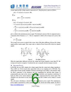
4) Phase Error Between Channels
The HPF (High Pass Filter) in Channel 1 has a phase lead response. To offset this phase response
and equalize the phase response between channels, a phase correction network is also placed in
Channel 1. The phase correction network matches the phase to within ±0.1°over a range of 45
Hz to 65 Hz and ±0.2°over a range 40Hz to 1KHz.
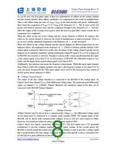
5) Gain Error
The gain error of the BL6506 is defined as the difference between the measured output frequency
(minus the offset) and the ideal output frequency. It is measured with a gain of 1 in channel V1.
The difference is expressed as a percentage of the ideal frequency. The ideal frequency is obtained
from the BL6506 transfer function.
6) Gain Error Match
The gain error match is defined as the gain error (minus the offset) obtained when switching
between a gain of 1 and a gain of 16. It is expressed as a percentage of the output frequency
obtained under a gain of 1. This gives the gain error observed when the gain selection is changed
from 1 to 16.
http://www.belling.com.cn
- 4 -
3/15/2007
Total 14 Pages

 BELLING [ BELLING ]