SinglePhaseEnergyMeterIC
with Integrated Oscillator
BL6506
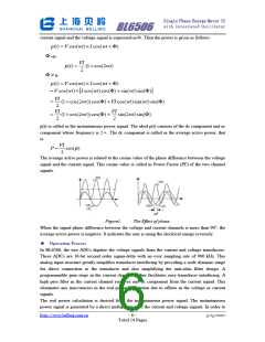
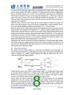
As can be seen, for each phase input, if there are simultaneous dc offsets on the voltage channel
and the current channel, these offsets contribute a dc component for the result of multiplication.
That is, the offsets bring the error of Uoffset
there exists the component of Uoffset
power will result in measure error, and the component brought to the frequency of
×
Ioffset to the final average real power. Additionally,
Ioffset at the frequency of . The dc error on the real
will also
×
I+
U
×
ω
ω
affect the output of the average active power when the next low-pass filter cannot restrain the ac
component very completely.
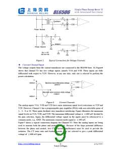
When the offset on the one of the voltage and the current channels is filtered, for instance, the
offset on the current channel is removed; the result of multiplication is improved greatly. There is
no dc error, and the additional component at the frequency of
When the offsets on the voltage channel and the current channel are filtered respectively by two
high-pass filters, the component at the frequency of (50Hz) is subdued, and the stability of the
ω is also decreased.
ω
output signal is advanced. Moreover, in this case, the phases of the voltage channel and the current
channel can be matched completely, and the performance when PF equal 0.5C or 0.5L is improved.
In BL6506, this structure is selected. Though it is given in the system specification that the ripple
of the output signal is less than 0.1%, in real measure of BL6506, the calibration output is very
stable, and the ripple of the typical output signal is less than 0.05%.
Additionally, this structure can ensure the frequency characteristic. When the input signal changes
from 45Hz to 65Hz, the complete machine error due to the frequency change is less than 0.1%. In
such, the meter designed for the 50Hz input signal can be used on the transmission-line system of
electric power whose frequency is 60Hz.
ꢀ
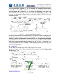
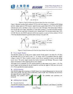
Voltage Channel Input
The output of the line voltage transducer is connected to the BL6506 at this analog input. As
Figure4 shows that channel V2 is a fully differential voltage input. The maximum peak differential
signal on Channel 2 is
±660mV. Figure4 illustrates the maximum signal levels that can be
connected to the BL6506 Voltage Channel.
V1
V1A
V1N
V1B
+660mV
+
-
GAIN
Maximun input differential voltage
V1
±660mV
V2
-
V2
V1
Maximun input common-mode voltage
±100mV
-660mV
GAIN
+
AGND
Figure 4.
Voltage Channels
Voltage Channel must be driven from a common-mode voltage, i.e., the differential voltage signal
on the input must be referenced to a common mode (usually GND). The analog inputs of the
BL6506 can be driven with common-mode voltages of up to 100 mV with respect to GND.
However, best results are achieved using a common mode equal to GND.
Figure5 shows two typical connections for Channel V2. The first option uses a PT (potential
transformer) to provide complete isolation from the mains voltage. In the second option, the
BL6506 is biased around the neutral wire and a resistor divider is used to provide a voltage signal
that is proportional to the line voltage. Adjusting the ratio of Ra and Rb is also a convenient way
of carrying out a gain calibration on the meter.
http://www.belling.com.cn
- 8 -
3/15/2007
Total 14 Pages

 BELLING [ BELLING ]