PCM1808
www.ti.com
SLES177A–APRIL 2006–REVISED AUGUST 2006
SERIAL AUDIO DATA INTERFACE
The PCM1808 interfaces the audio system through LRCK (pin 7), BCK (pin 8), and DOUT (pin 9).
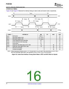
INTERFACE MODE
The PCM1808 supports master mode and slave mode as interface modes, which are selected by MD1 (pin 11)
and MD0 (pin 10), as shown in Table 2. MD1 and MD0 must be set prior to power on.
In master mode, the PCM1808 provides the timing of serial audio data communications between the PCM1808
and the digital audio processor or external circuit. While in slave mode, the PCM1808 receives the timing for
data transfer from an external controller.
Table 2. Interface Modes
MD1 (Pin 11)
Low
MD0 (Pin 10)
Low
INTERFACE MODE
Slave mode (256 fS, 384 fS, 512 fS autodetection)
Master mode (512 fS)
Low
High
High
Low
Master mode (384 fS)
High
High
Master mode (256 fS)
Master mode
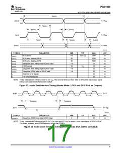
In master mode, BCK and LRCK work as output pins, and these pins are controlled by timing which is generated
in the clock circuit of the PCM1808. The frequency of BCK is fixed at 64 BCK/frame.
Slave mode
In slave mode, BCK and LRCK work as input pins. The PCM1808 accepts 64-BCK/frame or 48-BCK/frame
format (only for a 384-fS system clock), not 32-BCK/frame format.
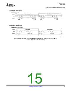
DATA FORMAT
The PCM1808 supports two audio data formats in both master and slave modes. The data formats are selected
by FMT (pin 12), as shown in Table 3. Figure 21 illustrates the data formats in slave mode and master mode.
Table 3. Data Format
FORMAT NO.
FMT (Pin 12)
Low
FORMAT
0
1
I2S, 24-bit
High
Left-justified, 24-bit
14
Submit Documentation Feedback

 BB [ BURR-BROWN CORPORATION ]