ꢀ
ꢁ
ꢂ
ꢃ
ꢄ
ꢅ
ꢆ
www.ti.com
SLES100 − DECEMBER 2003
LRCK
BCK
DID
Command Field
DI
Device ID = 1
Device ID = 2
DCO1
DCO1
DCI2
Device ID = 3
DCO2
DCI3
•
•
•
•
•
•
58 BCKs
Device ID = 30 DCO29
DCI30
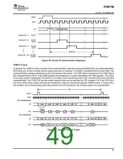
Figure 56. Device ID Determination Sequence
TDMCA Frame
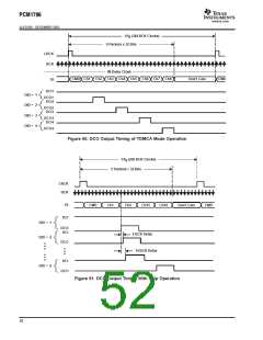
In general, the TDMCA frame consists of the command field, extended command (EMD) field, and audio data fields.
All of them are 32 bits in length, but the lowest byte has no meaning. The MSB is transferred first for each field. The
command field is always transferred as the first packet of the frame. The EMD field is transferred if the EMD flag of
the command field is HIGH. If any EMD packets are transferred, no audio data follows the EMD packets. This frame
is for quick system initialization. All devices of a daisy chain should respond to the command field and extended
command field. The PCM1796 has two audio channels that can be selected by OPE (register 19). If the OPE bit is
not set to HIGH, those audio channels are transferred. Figure 57 shows the general TDMCA frame. If some DACs
are enabled, but corresponding audio data packets are not transferred, the analog outputs are unpredictable.
1/f
S
LRCK
BCK
[For Initialization]
Don’t
Care
DI
EMD
CMD
CMD
EMD
EMD
CMD
EMD
EMD
32 Bits
DO
CMD
CMD
CMD
CMD
CMD
CMD
[For Operation]
Don’t
Care
Ch(n)
Ch2
Ch2
Ch4
Ch4
CMD
Ch1
Ch1
Ch3
Ch3
DI
DO
CMD
Ch(m)
Figure 57. General TDMCA Frame
49

 BB [ BURR-BROWN CORPORATION ]