ꢀ ꢁꢂ ꢃ ꢄ ꢅ ꢆ
www.ti.com
SLES100 − DECEMBER 2003
1/f (256 BCK Clocks)
S
7 Packets × 32 Bits
LRCK
BCK
Don’t
Care
DI
CMD
Ch2
IN and OUT Channel Orders are Completely Independent
Ch1 Ch2
Ch4
Ch5
Ch6
Ch1
CMD
Ch3
DO
CMD
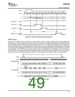
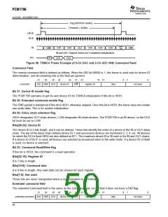
Figure 58. TDMCA Frame Example of 6-Ch DAC and 2-Ch ADC With Command Read
Command Field
The normal command field is defined as follows. When the DID bit (MSB) is 1, this frame is used only for device ID
determination, and all remaining bits in the field are ignored.
31
30
29
28
24
23
22
16 15
8
7
0
command
DID EMD DCS
device ID
R/W
register ID
data
not used
Bit 31: Device ID enable flag
The PCM1796 operates to get its own device ID for TDMCA initialization if this bit is HIGH.
Bit 30: Extended command enable flag
The EMD packet is transferred if this bit is HIGH, otherwise skipped. Once this bit is HIGH, this frame does not contain
any audio data. This is for system initialization.
Bit 29: Daisy chain selection flag
HIGH designates OUT-chain devices, LOW designates IN-chain devices. The PCM1796 is an IN device, so the DCS
bit must be set to LOW.
Bits[28:24]: Device ID
The device ID is 5 bits length, and it can be defined. These bits identify the order of a device in the IN or OUT daisy
chain. The top of the daisy chain defines device ID 1 and successive devices are numbered 2, 3, 4, etc. All devices
for which the DCI is fixed HIGH are also defined as ID 1. The maximum device ID is 30 each in the IN and OUT chains.
If a device ID of 0x1F is used, all devices are selected as broadcast when in the write mode. If a device ID of 0x00
is used, no device is selected.
Bit 23: Command Read/Write flag
If this bit is HIGH, the command is a read operation.
Bits[22:16]: Register ID
It is 7 bits in length.
Bits[15:8]: Command data
It is 8 bits in length. Any valid data can be chosen for each register.
Bits[7:0]: Not used
These bits are never transported when a read operation is performed.
Extended command field
The extended command field is the same as the command field, except that it does not have a DID flag.
31
30
29
28
24
23
22
16 15
8
7
0
extended command rsvd EMD DCS
device ID
R/W
register ID
data
not used
50

 BB [ BURR-BROWN CORPORATION ]