ꢀ
ꢁ
ꢂ
ꢃ
ꢄ
ꢅ
ꢆ
www.ti.com
SLES100 − DECEMBER 2003
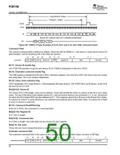
Audio Fields
The audio field is 32 bits in length and the audio data is transferred MSB first, so the other fields must be stuffed with
0s as shown in the following example.
31
16
12
8
7
4 3
0
audio data MSB
24 bits
LSB
All 0s
TDMCA Register Requirements
TDMCA mode requires device ID and audio channel information, previously described. The OPE bit in register 19
indicates audio channel availability and register 23 indicates the device ID. Register 23 is used only in the TDMCA
mode. See the mode control register map (Table 4).
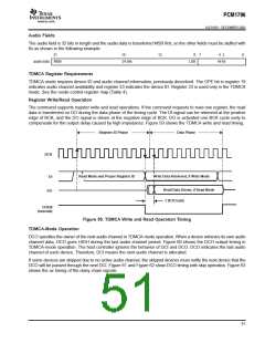
Register Write/Read Operation
The command supports register write and read operations. If the command requests to read one register, the read
data is transferred on DO during the data phase of the timing cycle. The DI signal can be retrieved at the positive
edge of BCK, and the DO signal is driven at the negative edge of BCK. DO is activated one BCK cycle early to
compensate for the output delay caused by high impedance. Figure 59 shows the TDMCA write and read timing.
Register ID Phase
Data Phase
BCK
Read Mode and Proper Register ID
Write Data Retrieved, if Write Mode
DI
Read Data Driven, if Read Mode
1 BCK Early
DO
DOEN
(Internal)
Figure 59. TDMCA Write and Read Operation Timing
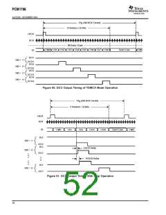
TDMCA-Mode Operation
DCO specifies the owner of the next audio channel in TDMCA-mode operation. When a device retrieves its own audio
channel data, DCO goes HIGH during the last audio channel period. Figure 60 shows the DCO output timing in
TDMCA-mode operation. The host controller ignores the behavior of DCI and DCO. DCO indicates the last audio
channel of each device. Therefore, DCI means the next audio channel is allocated.
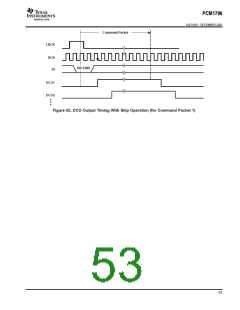
If some devices are skipped due to no active audio channel, the skipped devices must notify the next device that the
DCO will be passed through the next DCI. Figure 61 and Figure 62 show DCO timing with skip operation. Figure 63
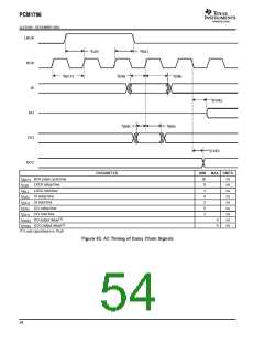
shows the ac timing of the daisy chain signals.
51

 BB [ BURR-BROWN CORPORATION ]