ꢀ ꢁꢂ ꢃ ꢄ ꢅ ꢆ
www.ti.com
SLES100 − DECEMBER 2003
TDMCA INTERFACE FORMAT
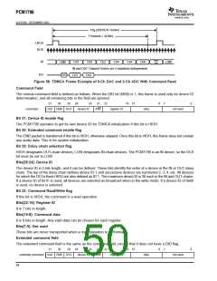
The PCM1796 supports the time-division-multiplexed command and audio (TDMCA) data format to simplify the host
control serial interface. The TDMCA format is designed not only for the McBSP of TI DSPs but also for any
programmable devices. The TDMCA format can transfer not only audio data but also command data, so that it can
be used together with any kind of device that supports the TDMCA format. The TDMCA frame consists of a command
field, extended command field, and some audio data fields. Those audio data are transported to IN devices (such
as a DAC) and/or from OUT devices (such as an ADC). The PCM1796 is an IN device. LRCK and BCK are used
with both IN and OUT devices so that the sample frequency of all devices in a system must be the same. The TDMCA
mode supports a maximum of 30 device IDs. The maximum number of audio channels depends on the BCK
frequency.
TDMCA Mode Determination
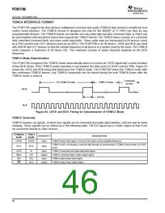
The PCM1796 recognizes the TDMCA mode automatically when it receives an LRCK signal with a pulse duration
of two BCK clocks. If the TDMCA mode operation is not needed, the duty cycle of LRCK must be 50%. Figure 53
shows the LRCK and BCK timing that determines the TDMCA mode. The PCM1796 enters the TDMCA mode after
two continuous TDMCA frames. Any TDMCA commands can be issued during the next TDMCA frame after the
TDMCA mode is entered.
Command
Accept
Pre-TDMCA Frame
TDMCA Frame
LRCK
2 BCKs
BCK
Figure 53. LRCK and BCK Timing for Determination of TDMCA Mode
TDMCA Terminals
TDMCA requires six signals, of which four signals are for command and audio data interface, and one pair for daisy
chaining. Those signals can be shared as in the following table. The DO signal has a 3-state output so that it can
be connected directly to other devices.
TERMINAL TDMCA
PROPERTY
input
DESCRIPTION
NAME
NAME
LRCK
LRCK
TDMCA frame start signal. It must be the same as the sampling frequency.
TDMCA clock. Its frequency must be high enough to communicate a TDMCA frame within an LRCK
cycle.
BCK
BCK
input
DATA
MDO
MC
DI
DO
input
output
input
TDMCA command and audio data input signal
TDMCA command data 3-state output signal
TDMCA daisy-chain input signal
DCI
DCO
MS
output
TDMCA daisy-chain output signal
46

 BB [ BURR-BROWN CORPORATION ]