ꢀ
ꢁ
ꢂ
ꢃ
ꢄ
ꢅ
ꢆ
www.ti.com
SLES100 − DECEMBER 2003
Device ID Determination
The TDMCA mode also supports a multichip implementation in one system. This means a host controller (DSP) can
simultaneously support several TDMCA devices, which can be of the same type or different types, including PCM
devices. The PCM devices are categorized as IN device, OUT device, IN/OUT device, and NO device. The IN device
has an input port to receive audio data, the OUT device has an output port to supply audio data, the IN/OUT device
has both input and output ports for audio data, and the NO device has no port for audio data but needs command
data from the host. A DAC is an IN device, an ADC is an OUT device, a codec is an IN/OUT device, and a PLL is
a NO device. The PCM1796 is an IN device. For the host controller to distinguish the devices, each device is assigned
its own device ID by the daisy chain. The devices obtain their own device IDs automatically by connecting their DCI
to the DCO of the preceding device and their DCO to the DCI of the following device in the daisy chain. The daisy
chains are categorized as the IN chain and the OUT chain, which are completely independent and equivalent.
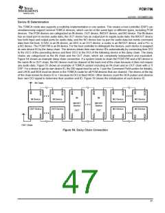
Figure 54 shows an example daisy chain connection. If a system needs to chain the PCM1796 and a NO device in
the same IN or OUT chain, the NO device must be chained at the back end of the chain because it does not require
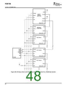
any audio data. Figure 55 shows an example of TDMCA system including an IN chain and an OUT chain with a TI
DSP. For a device to get its own device ID, the DID signal must be set to 1 (see the Command Field section for details),
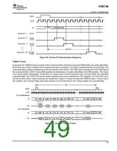
and LRCK and BCK must be driven in the TDMCA mode for all PCM devices that are chained. The device at the top
of the chain knows its device ID is 1 because its DCI is fixed HIGH. Other devices count the BCK pulses and observe
their own DCI signal to determine their position and ID. Figure 56 shows the initialization of each device ID.
IN Chain
• • •
• • •
• • •
• • •
IN
IN
IN Device
IN Device
NO Device
NO Device
NO Device
NO Device
IN/OUT
Device
IN/OUT
Device
• • •
OUT Device
OUT Device
OUT
OUT
OUT Chain
Figure 54. Daisy Chain Connection
47

 BB [ BURR-BROWN CORPORATION ]