ꢀ ꢁꢂ ꢃ ꢄꢅ ꢆ
www.ti.com
SLES100 − DECEMBER 2003
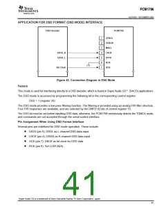
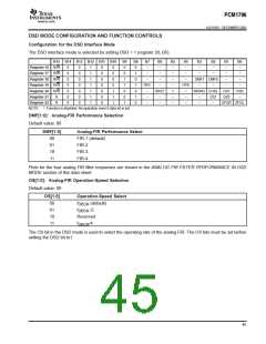
DSD MODE CONFIGURATION AND FUNCTION CONTROLS
Configuration for the DSD Interface Mode
The DSD interface mode is selected by setting DSD = 1 (register 20, B5).
B15 B14 B13 B12 B11 B10
B9
0
B8
0
B7
−
B6
B5
−
B4
−
B3
−
B2
−
B1
−
B0
−
Register 16 R/W
Register 17 R/W
Register 18 R/W
Register 19 R/W
Register 20 R/W
0
0
0
0
0
0
0
0
0
0
0
0
0
0
1
1
1
1
1
1
1
0
0
0
0
0
0
0
0
0
0
0
1
1
1
−
0
1
−
−
−
−
−
−
−
−
1
0
−
−
−
−
DMF1 DMF0
−
−
1
1
REV
−
−
SRST
−
−
OPE
−
−
−
−
−
0
0
1
MONO CHSL OS1
OS0
−
Register 21
Register 22
R
R
0
1
−
−
−
−
−
DZ1
−
DZ0
1
0
−
−
−
−
ZFGR ZFGL
NOTE: −: Function is disabled. No operation even if data bit is set
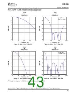
DMF[1:0]: Analog-FIR Performance Selection
Default value: 00
DMF[1:0]
Analog-FIR Performance Select
00
01
10
11
FIR-1 (default)
FIR-2
FIR-3
FIR-4
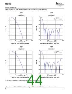
Plots for the four analog FIR filter responses are shown in the ANALOG FIR FILTER PERFORMANCE IN DSD
MODE section of this data sheet.
OS[1:0]: Analog-FIR Operation-Speed Selection
Default value: 00
OS[1:0]
00
Operation-Speed Select
f
f
(default)
/2
DBCK
DBCK
01
10
Reserved
f /4
DBCK
11
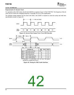
The OS bit in the DSD mode is used to select the operating rate of the analog FIR. The OS bits must be set before
setting the DSD bit to1.
45

 BB [ BURR-BROWN CORPORATION ]