ꢀ ꢁꢂ ꢃ ꢄꢅ ꢆ
www.ti.com
SLES100 − DECEMBER 2003
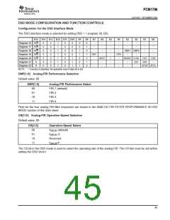
APPLICATION FOR DSD FORMAT (DSD MODE) INTERFACE
DSD Decoder
PCM1796
ZEROL
ZEROR
MSEL
LRCK
DATA
BCK
1
2
3
DATA_R
DATA_L
4
5
6
7
Bit Clock
SCK
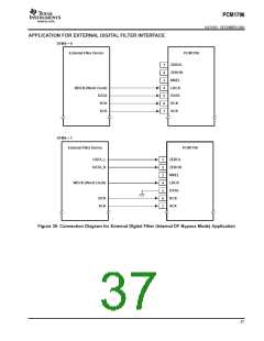
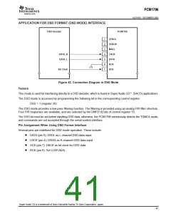
Figure 42. Connection Diagram in DSD Mode
Feature
This mode is used for interfacing directly to a DSD decoder, which is found in Super Audio CDt (SACD) applications.
The DSD mode is accessed by programming the following bit in the corresponding control register.
DSD = 1 (register 20)
The DSD mode provides a low-pass filtering function. The filtering is provided using an analog FIR filter structure.
Four FIR responses are available, and are selected by the DMF[1:0] bits of control register 18.
The DSD bit must be set before inputting DSD data; otherwise, the PCM1796 erroneously detects the TDMCA mode,
and commands are not accepted through the serial control interface.
Pin Assignment When Using DSD Format Interface
Several pins are redefined for DSD mode operation. These include:
D DATA (pin 5): DSDL as L-channel DSD data input
D LRCK (pin 4): DSDR as R-channel DSD data input
D SCK (pin 7): DBCK as bit clock for DSD data
D BCK (pin 6): Set LOW (N/A)
Super Audio CD is a trademark of Sony Kabushiki Kaisha TA Sony Corporation, Japan.
41

 BB [ BURR-BROWN CORPORATION ]