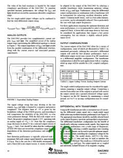
Figure 8 shows an example of a DC-coupled interface with
DC level-shifting, using a precision resistor network. An ac-
coupled interface, as shown in Figure 9, has the advantage
that the common-mode levels at the input of the modulator
can be set independently of those at the output of the DAC.
Furthermore, no voltage loss is obtained in this setup.
VDC
R3
VOUT
VOUT
1
1
INTERNAL REFERENCE OPERATION
The DAC2902 has an on-chip reference circuit that com-
prises a 1.25V bandgap reference and two control amplifi-
R4
IOUT
1
DAC2902
ers, one for each DAC. The full-scale output current, IOUTFS
,
IOUT
1
1
of the DAC2902 is determined by the reference voltage,
VREF, and the value of resistor RSET. IOUTFS can be calcu-
lated by:
IOUT
1
IOUT
IOUTFS = 32 • IREF = 32 • VREF / RSET
(10)
R5
The external resistor RSET connects to the FSA pin (Full-
Scale Adjust), see Figure 10. The reference control amplifier
operates as a V-to-I converter producing a reference current,
IREF, which is determined by the ratio of VREF and RSET (as
FIGURE 8. DC-Coupled Interface to Quadrature Modulator
Applying Level Shifting.
shown in Equation 10). The full-scale output current, IOUTFS
,
results from multiplying IREF by a fixed factor of 32.
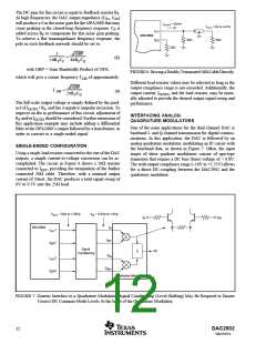
VDC
R1
IOUT
1
DAC2902
0.01µF
IOUT
1
VOUT
VOUT
1
1
IOUT
1
0.01µF
I
OUT1
50Ω
50Ω
RLOAD
R2
FIGURE 9. AC-Coupled Interface to Quadrature Modulator Applying Level Shifting.
DAC2902
SBAS167A
13

 BB [ BURR-BROWN CORPORATION ]