CALIBRATION
settling filter for the next two conversions, the first of which
should be discarded. It will then use the sinc2 followed by the
sinc3 filter to improve noise performance. This combines the
low-noise advantage of the sinc3 filter with the quick response
of the fast settling time filter. The frequency response of each
filter is shown in Figure 3.
The offset and gain errors in the ADS1218, or the complete
system, can be reduced with calibration. Internal calibration of
the ADS1218 is called self calibration. This is handled with
three commands. One command does both offset and gain
calibration. There is also a gain calibration command and an
offset calibration command. Each calibration process takes
seven tDATA periods to complete. Therefore, it takes 14 tDATA
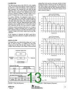
SINC3 FILTER RESPONSE
(–3dB = 0.262 • fDATA = 15.76Hz)
periods to complete both an offset and gain calibration.
0
For system calibration, the appropriate signal must be
applied to the inputs. The system offset command requires a
“zero” differential input signal. It then computes an offset that
will nullify offset in the system. The system gain command
requires a positive “full-scale” differential input signal. It then
computes a value to nullify gain errors in the system. Each of
these calibrations will take seven tDATA periods to complete.
–20
–40
–60
–80
Calibration should be performed after power on, a change in
temperature, a change in decimation ratio, or a change in the
PGA. Calibration will remove the offset in the ODAC register.
Therefore, changes to the ODAC register must be done after
calibration.
–100
–120
0
0
0
30
30
30
60 90 120 150 180 210 240 270 300
Frequency (Hz)
At the completion of calibration, the DRDY signal will go
LOW to indicate that calibration is complete and valid data is
available.
SINC2 FILTER RESPONSE
(–3dB = 0.318 • fDATA = 19.11Hz)
0
–20
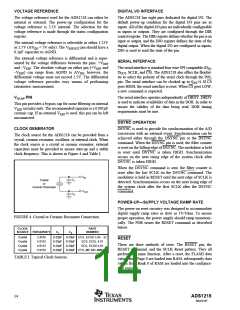
DIGITAL FILTER
The Digital Filter can use either the fast settling, sinc2, or sinc3
filter, as shown in Figure 2. In addition, the Auto mode
changes the sinc filter after the input channel or PGA is
changed. When switching to a new channel, it will use the fast
–40
–60
–80
Adjustable Digital Filter
Sinc3
–100
–120
60 90 120 150 180 210 240 270 300
Frequency (Hz)
Modulator
Output
Sinc2
Data Out
FAST SETTLING FILTER RESPONSE
(–3dB = 0.469 • fDATA = 28.125Hz)
0
–20
Fast Settling
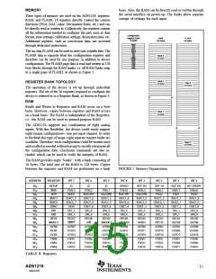
FILTER SETTLING TIME
FILTER
–40
SETTLING TIME
(Conversion Cycles)
–60
Sinc3
Sinc2
Fast
3(1)
2(1)
1(1)
–80
–100
–120
NOTE: (1) With Synchronized Channel Changes.
AUTO MODE FILTER SELECTION
CONVERSION CYCLE
60 90 120 150 180 210 240 270 300
Frequency (Hz)
1
2
3
4+
Discard
Fast
Sinc2
Sinc3
NOTE: fDATA = 60Hz.
FIGURE 2. Filter Step Responses.
FIGURE 3. Filter Frequency Responses.
ADS1218
13
SBAS187

 BB [ BURR-BROWN CORPORATION ]