SMPS Capacitors
Assembly Guidelines
®
If bonding the SupraCap to the board with adhesive, consider-
Reliability
ation of the CTE (coefficient of thermal expansion) is necessary.
A mismatch between the CTE of the ceramic and adhesive can
cause the ceramic to crack during temperature cycles.
AVX has been involved in numerous military and customer High
Reliability programs for over 40 years.
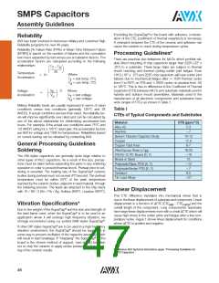
Reliability [ꢀ Failure Rate (FRꢀ) or Mean Time Between Failure
(MTBF)] is based on the number of failures and the cumulative
test hours expanded by test versus use acceleration factors. The
acceleration factors are calculated according to the following
relationships:
Processing Guidelines*
There are practical size limitations for MLCs which prohibit reli-
able direct mounting of chip capacitors larger than 2225 (.22" x
.25") to a substrate. These large chips are subject to thermal
shock cracking and thermal cycling solder joint fatigue. Even
1812 (.18" x .12") and 2225 chip capacitors will have solder joint
failures due to mechanical fatigue after ꢂ 1500 thermal cycles
from 0 to 85°C on FR4 and ꢂ 3000 cycles on alumina from -55
to 125°C. This is due to differences in the Coefficient of Thermal
Expansion (CTE) between MLCs and substrate materials used in
hybrids and surface mount assemblies. Materials used in the
manufacture of all electronic components and substrates have
wide ranges of CTEs as shown in Table 1.
T
– T
25
T
U
Temperature
Acceleration
Where:
= 10
T
T
= test temp. (°C)
= use temp. (°C)
T
U
Voltage
Acceleration
V
V
3
Where:
T
u
=
V
V
= test voltage
= use voltage
T
U
Military Reliability levels are usually expressed in terms of rated
conditions versus test conditions (generally 125°C and 2X
WVDC). If actual conditions are less than rated, the reliability lev-
els will improve significantly over rated and can be calculated by
use of the above relationship for determining accelerated test
hours. For example, if the actual use conditions were 75°C and
1/2 WVDC rating for a 125°C rated part, the acceleration factors
are 64X for voltage and 100X for temperature. Reliabilities based
on current testing can be obtained by contacting AVX.
Table I
CTEs of Typical Components and Substrates
Material
CTE (ppm/°C)
5.3
Alloy 42
Alumina
ꢃ7
Barium Titanate Capacitor Body
Copper
10-12
17.6
6-7
General Processing Guidelines
Soldering
Copper Clad Invar
Filled Epoxy Resin (<T )
18-25
ꢃ18
15
R
FR4/G-10 PC Board (X, Y)
Nickel or Steel
The SM styles capacitors are generally quite large relative to
other types of MLC capacitors. As a result of the size, precau-
tions must be taken before subjecting the parts to any soldering
operation in order to prevent thermal shock. Preheat prior to sol-
Polyimide/Glass PCB (X, Y)
Polyimide/Kevlar PCB (X, Y)
Tantalum
ꢃ12
ꢃ7
6.5
®
dering is essential. The heating rate of the SupraCap ceramic
bodies during preheat must not exceed 4°C/second. The preheat
temperature must be within 50°C of the peak temperature
reached by the ceramic bodies, adjacent to lead material, through
the soldering process. The leads are attached to the chip stack
with 10 / 88 / 2 (Sn / Pb / Ag, Solidus 268°C, Liquidus 290°C).
Tin Lead Alloys
ꢃ27
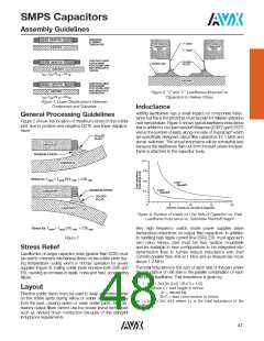
Linear Displacement
This CTE difference translates into mechanical stress that is
due to the linear displacement of substrate and component. Linear
displacement is a function of ⌬CTE (CTE
– CTE ) and the
Vibration Specifications*
sub
comp
overall length of the component. Long components/ substrates
have large linear displacements even with a small ⌬CTE which will
cause high stress in the solder joints and fatigue after a few tem-
perature cycles. Figure 1 shows linear displacement for conditions
where ⌬CTE is positive and negative.
®
Due to the weight of the SupraCap and the size and strength of
®
the lead frame used, when the SupraCap is to be used in an
application where it will undergo high frequency vibration, we
strongly recommend using our potted SM9 styles SupraCap .
®
®
If other DIP styles SupraCap are to be used in a high frequency
®
vibration environment, the SupraCap should be supported in
some way to prevent oscillation of the capacitor assembly which
®
will result in lead breakage. If “strapping” the SupraCap to the
board is the chosen method of support, care should be taken
not to chip the ceramic or apply undue pressure so that crack-
ing of the ceramic results.
* Reference AVX Technical Information paper, “Processing Guidelines for
SMPS Capacitors.”
46

 KYOCERA AVX [ KYOCERA AVX ]