SMPS Capacitors (RH Style)
RH - Surface Mount ‘J’ Lead Range
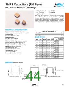
0.047 μF to 47.0 μF
Low ESR/ESL
X7R Dielectric
25V to 500 VDC
-55ºC to +125ºC
This range of uncoated MLC capacitors are processed for
input and output filter capacitors in high frequency DC-DC
convertor applications above 10 Watts e.g. telecomms and
instrumentation, where high volume and low cost is required.
These products are available in surface mount ‘J’ leaded
versions and can be supplied in bulk and tape/reel packaging.
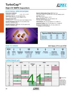
ELECTRICAL SPECIFICATIONS
Temperature Coefficient CECC 30 000, (4.24.1)
Typical ESR (mΩ) 3 μF, 100V X7R
ESR @ 100KHz
ESR @ 500KHz
ESR @ 1MHz
17
12
14
X7R: C Temperature Characteristic - 15ꢀ, -55ºC to +125ºC
Capacitance Test
Measured at 1 VRMS max at 1KHz
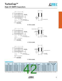
DIMENSIONS
millimeters (inches)
No. of leads
Dissipation Factor 25°C
2.5ꢀ max at 1KHz, 1 VRMS max
S
0.1
Style L max
W max H max
h
( 0.004)
per side
Insulation Resistance 25°C
100K megohms or 1000 megohms-μF, whichever is less
1.50 0.30
(0.059 0.012)
RH21
RH22
RH31
RH32
RH41
RH42
RH51
RH52
RH61
RH62
7.62 (0.300) 5.40 (0.213) 4.60 (0.181) 2.50 (0.098)
7.62 (0.300) 5.40 (0.213) 7.50 (0.295) 2.50 (0.098)
7.62 (0.300) 7.00 (0.270) 5.08 (0.200) 5.08 (0.200)
7.62 (0.300) 7.00 (0.270) 8.13 (0.320) 5.08 (0.200)
9.20 (0.362) 8.70 (0.342) 4.90 (0.192) 5.08 (0.200)
9.20 (0.362) 8.70 (0.342) 8.20 (0.323) 5.08 (0.200)
10.7 (0.421) 10.7 (0.421) 4.90 (0.192) 7.62 (0.300)
10.7 (0.421) 10.7 (0.421) 8.20 (0.323) 7.62 (0.300)
14.9 (0.586) 13.6 (0.535) 4.90 (0.192) 10.2 (0.400)
14.9 (0.586) 13.6 (0.535) 8.20 (0.323) 10.2 (0.400)
2
1.50 0.30
(0.059 0.012)
Dielectric Withstanding Voltage 25°C (Flash Test)
250ꢀ rated voltage for 5 seconds with 50 mA max
charging current. (500 Volt units @ 150ꢀ rated voltage)
2
1.78 0.25
(0.070 0.010)
3
1.78 0.25
(0.070 0.010)
3
Life Test (1000 hrs) CECC 30 000 (4.23)
200ꢀ rated voltage at +125ºC.
(500 Volt units @ 120ꢀ rated voltage)
1.60 0.10
(0.062 0.004)
3
1.60 0.10
(0.062 0.004)
3
Thermal Shock IEC 68.2.14
-55ºC to +125ºC, 5 cycles
1.60 0.10
(0.062 0.004)
4
Resistance to Solder Heat IEC 68.2.20
1.60 0.10
(0.062 0.004)
4
1.60 0.10
(0.062 0.004)
5
1.60 0.10
(0.062 0.004)
5
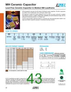
DIMENSIONS millimeters (inches)
0.6 (0.024)
0.1 (0.004)
L Max.
W Max.
M1
M1 = M2 0.5 (0.020)
M2
H Max.
h
2.54 (0.100)
0.05 (0.002)
Non-Accum.
1.4 (0.055) Typ.
1.65 (0.065) 0.15 (0.006)
0.25 (0.010)Typ.
S
Bend Radius
90° 5°
43

 KYOCERA AVX [ KYOCERA AVX ]