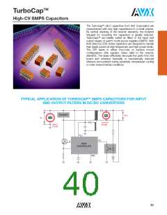
TM
TurboCap
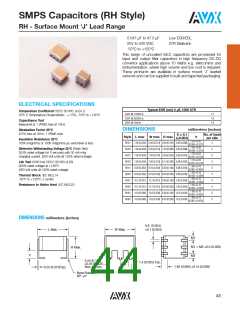
High-CV SMPS Capacitors
ELECTRICAL SPECIFICATIONS
Temperature Coefficient
Dielectric Withstanding Voltage 25°C (Flash Test)
Temperature Coefficient
15ꢀ, -55° to +125°C
250ꢀ rated voltage for 5 seconds with 50 mA max charging current.
Capacitance Test (MIL-STD-202 Method 305)
Life Test (1000 hrs)
25°C, 1.0 0.2 Vrms (open circuit voltage) at 1KHz
X7R: 150ꢀ rated voltage at +125°C.
Dissipation Factor 25°C
Moisture Resistance (MIL-STD-202 Method 106)
2.5ꢀ Max @ 25°C, 1.0 0.2 Vrms (open circuit voltage) at 1KHz
Ten cycles with no voltage applied.
Insulation Resistance 25°C (MIL-STD-202 Method 302)
500 MΩ-μF, whichever is less.
Thermal Shock (MIL-STD-202 Method 107, Condition A)
Immersion Cycling (MIL-STD-202 Method 104, Condition B)
Insulation Resistance 125°C (MIL-STD-202 Method 302)
50 MΩ-μF, whichever is less.
Resistance To Solder Heat (MIL-STD-202, Method 210,
Condition B, for 20 seconds)
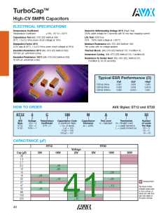
Typical ESR Performance (Ω)
27μF
0.007
0.003
0.002
47μF
0.004
0.002
0.0015
100μF
0.003
0.0015
0.001
ESR @ 10KHz
ESR @ 50KHz
ESR @ 100KHz
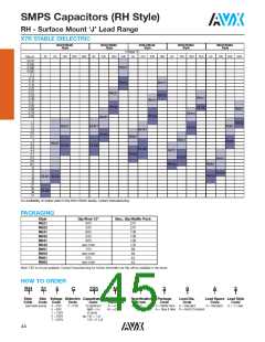
HOW TO ORDER
AVX Styles: ST12 and ST20
ST12
5
C
186
M
A
N
03
AVX
Style
ST12
ST20
Voltage
25V = 3
50V = 5
100V = 1
Temperature
Coefficient
X7R = C
Capacitance Code
(2 significant digits
+ no. of zeros)
1 μF = 105
Capacitance
Tolerance
M = 20ꢀ
Test Level
A = Standard
Termination
Number
of Leads
Per Side
03 = 3
N = Straight Lead
J = Leads formed in
L = Leads formed out
10 μF = 106
05 = 5
100 μF = 107
10 = 10
CAPACITANCE (μF)
ST12
ST20
Voltage
Cap (μF)
.82
1.3
2.7
8.2
12
50V
100V
25V
50V
100V
500V
...03
...05
14
18
22
27
47
50
...03
...05
...10
...03
...05
...10
...10
Development
...03
...05
Numbers inside
shaded areas refer
to the number of
leads per side (the
last two digits of
the part number.
68
100
220
...03
...05
...10
...10
40

 KYOCERA AVX [ KYOCERA AVX ]