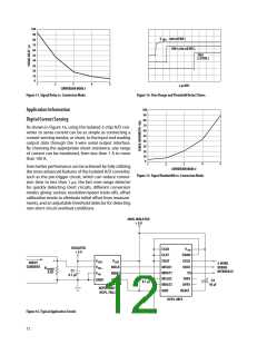
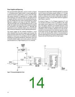
Product Description
The HCPL-7860/HCPL-786J Isolated Modulator (optocou-
pler) uses sigma-delta modulation to convert an analog
input signal into a high-speed (10 MHz) single-bit digital
data stream; the time average of the modulator’s single-
bit data is directly proportional to the input signal. The
isolated modulator’s other main function is to provide
galvanic isolation between the analog input and the digital
output. An internal voltage reference determines the full-
scale analog input range of the modulator (approximately
320 mV); an input range of 200 mV is recommended
to achieve optimal performance.
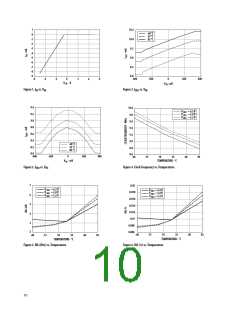
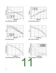
five conversion modes, which have different combina-
tions of speed and resolution to achieve the desired level
of performance. Other functions of the HCPL-0872 Digital
Interface IC include a Phase Locked Loop based pre-trigger
circuit that can either give more precise control of the ef-
fective sampling time or reduce conversion time to less
than 1 ꢄs, a fast over-range detection circuit that rapidly
indicates when the magnitude of the input signal is be-
yond full-scale, an adjustable threshold detection circuit
that indicates when the magnitude of the input signal is
above a user adjustable threshold level, an offset calibra-
tion circuit, and a second multiplexed input that allows a
second Isolated Modulator to be used with a single Digital
Interface IC.
HCPL-7860/HCPL-786J can be used together with HCPL-
0872, Digital Interface IC or a digital filter. The primary
functions of the HCPL-0872 Digital Interface IC are to de-
rive a multi-bit output signal by averaging the single-bit
modulator data, as well as to provide a direct microcon-
troller interface. The effective resolution of the multi-bit
output signal is a function of the length of time (measured
in modulator clock cycles) over which the average is taken;
averaging over longer periods of time results in higher
resolution. The Digital Interface IC can be configured for
The digital output format of the Isolated A/D Converter is
15 bits of unsigned binary data. The input full-scale range
and code assignment is shown in Table 1 below. Although
the output contains 15 bits of data, the effective resolution
is lower and is determined by selected conversion mode as
shown in Table 2 below.
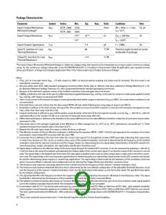
Table 1. Input Full-Scale Range and Code Assignment.
Analog Input
Full Scale Range
Minimum Step Size
+Full Scale
Voltage Input
640 mV
20 ꢀV
Digital Output
32768 LSBs
1 LSB
+320 mV
0 mV
111111111111111
100000000000000
000000000000000
Zero
-Full Scale
-320 mV
Table 2. Isolated A/D Converter Typical Performance Characteristics.
Conversion Time (μsꢀ
Pre-Trigger Mode
Signal-to-
Noise Ratio
(dBꢀ
Effective
Resolution
(bitsꢀ
Signal
Delay(μsꢀ
Signal Band-
width (kHzꢀ
Conversion Mode
0
1
2
1
83
79
73
66
53
13.5
12.8
11.9
10.7
8.5
205
102
102
51
19
10
5
3.4
6.9
22
45
90
2
3
4
5
103
39
51
19
10
5
0.2
20
10
Notes: Bold italic type indicates Default values.
13

 AVAGO [ AVAGO TECHNOLOGIES LIMITED ]