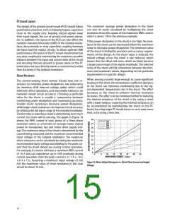
For a two-terminal shunt, as the value of shunt resistance the increased power dissipation at higher currents.
decreases, the resistance of the leads becomes a signifi-
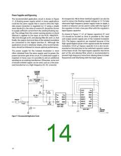
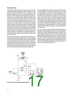
When laying out a PC board for the shunts, a couple of
cant percentage of the total shunt resistance. This has two
points should be kept in mind. The Kelvin connections
primary effects on shunt accuracy. First, the effective resis-
to the shunt should be brought together under the body
tance of the shunt can become dependent on factors such
of the shunt and then run very close to each other to the
as how long the leads are, how they are bent, how far they
input of the isolated modulator; this minimizes the loop
are inserted into the board, and how far solder wicks up
area of the connection and reduces the possibility of stray
the lead during assembly (these issues will be discussed in
magnetic fields from interfering with the measured signal.
more detail shortly). Second, the leads are typically made
If the shunt is not located on the same PC board as the
from a material such as copper, which has a much higher
isolated modulator circuit, a tightly twisted pair of wires
tempco than the material from which the resistive element
can accomplish the same thing.
itself is made, resulting in a higher tempco for the shunt
overall. Both of these effects are eliminated when a four- Also, multiple layers of the PC board can be used to in-
terminal shunt is used. A four-terminal shunt has two ad- crease current carrying capacity. Numerous plated-through
ditional terminals that are Kelvin-connected directly across
vias should surround each non-Kelvin terminal of the shunt
the resistive element itself; these two terminals are used to help distribute the current between the layers of the PC
to monitor the voltage across the resistive element while board. The PC board should use 2 or 4 oz. copper for the
the other two terminals are used to carry the load current.
layers, resulting in a current carrying capacity in excess of
Because of the Kelvin connection, any voltage drops across 20 A. Making the current carrying traces on the PC board
the leads carrying the load current should have no impact fairly large can also improve the shunt’s power dissipa-
on the measured voltage.
tion capability by acting as a heat sink. Liberal use of vias
where the load current enters and exits the PC board is
also recommended.
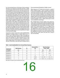
Several four-terminal shunts from Isotek (Isabellenhütte)
suitable for sensing currents in motor drives up to 71
Arms (71 hp or 53 kW) are shown in Table 3; the maximum
current and motor power range for each of the PBV series
shunts are indicated. For shunt resistances from 50 mꢆ
down to 10 mꢆ, the maximum current is limited by the
input voltage range of the isolated modulator. For the 5
mꢆ and 2 mꢆ shunts, a heat sink may be required due to
Table 3. Isotek (Isabellenhütteꢀ Four-Terminal Shunt Summary.
Maximum RMS Cur-
rent
Motor Power Range
120 V - 440 V
Shunt Resistance
Tol.
AC
AC
Shunt Resistor
Part Number
mꢆ
%
A
hp
kW
PBV-R050-0.5
PBV-R020-0.5
PBV-R010-0.5
PBV-R005-0.5
PBV-R002-0.5
50
0.5
3
0.8 - 3
2 - 7
0.6 - 2
0.6 - 2
20
10
5
0.5
0.5
0.5
0.5
7
14
4 - 14
3 - 10
25 [28]
39 [71]
7 - 25 [8 - 28]
11 - 39 [19 - 71]
5 - 19 [6 - 21]
8 - 29 [14 - 53]
2
Note: Values in brackets are with a heatsink for the shunt.
16

 AVAGO [ AVAGO TECHNOLOGIES LIMITED ]