PC Board Layout
The maximum average power dissipation in the shunt
can also be easily calculated by multiplying the shunt
resistance times the square of the maximum RMS current,
which is about 1 W in the previous example.
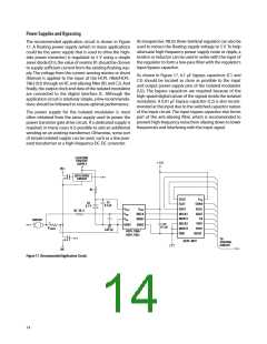
The design of the printed circuit board (PCB) should follow
good layout practices, such as keeping bypass capacitors
close to the supply pins, keeping output signals away
from input signals, the use of ground and power planes,
etc. In addition, the layout of the PCB can also affect the
isolation transient immunity (CMR) of the isolated modu-
lator, due primarily to stray capacitive coupling between
the input and the output circuits. To obtain optimal CMR
performance, the layout of the PC board should minimize
any stray coupling by maintaining the maximum possible
distance between the input and output sides of the circuit
and ensuring that any ground or power plane on the PC
board does not pass directly below or extend much wider
than the body of the isolated modulator.
If the power dissipation in the shunt is too high, the resis-
tance of the shunt can be decreased below the maximum
value to decrease power dissipation. The minimum value
of the shunt is limited by precision and accuracy require-
ments of the design. As the shunt value is reduced, the
output voltage across the shunt is also reduced, which
means that the offset and noise, which are fixed, become
a larger percentage of the signal amplitude. The selected
value of the shunt will fall somewhere between the mini-
mum and maximum values, depending on the particular
requirements of a specific design.
Shunt Resistors
When sensing currents large enough to cause significant
heating of the shunt, the temperature coefficient (tempco)
of the shunt can introduce nonlinearity due to the sig-
nal dependent temperature rise of the shunt. The effect
increases as the shunt-to-ambient thermal resistance
increases. This effect can be minimized either by reducing
the thermal resistance of the shunt or by using a shunt
with a lower tempco. Lowering the thermal resistance can
be accomplished by repositioning the shunt on the PC
board, by using larger PC board traces to carry away more
heat, or by using a heat sink.
The current-sensing shunt resistor should have low re-
sistance (to minimize power dissipation), low inductance
(to minimize di/dt induced voltage spikes which could
adversely affect operation), and reasonable tolerance (to
maintain overall circuit accuracy). Choosing a particular
value for the shunt is usually a compromise between
minimizing power dissipation and maximizing accuracy.
Smaller shunt resistances decrease power dissipation,
while larger shunt resistances can improve circuit accuracy
by utilizing the full input range of the isolated modulator.
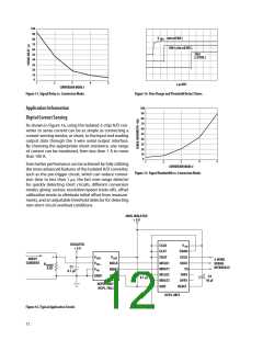
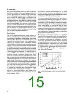
The first step in selecting a shunt is determining how much
current the shunt will be sensing. The graph in Figure 18
shows the RMS current in each phase of a three-phase
induction motor as a function of average motor output
power (in horsepower, hp) and motor drive supply volt-
age. The maximum value of the shunt is determined by the
current being measured and the maximum recommended
input voltage of the isolated modulator. The maximum
shunt resistance can be calculated by taking the maximum
recommended input voltage and dividing by the peak cur-
rent that the shunt should see during normal operation.
For example, if a motor will have a maximum RMS current
of 10 A and can experience up to 50% overloads during
normal operation, then the peak current is 21.1 A (= 10 x
1.414 x 1.5). Assuming a maximum input voltage of 200
mV, the maximum value of shunt resistance in this case
would be about 10 mꢆ.
40
440
35
30
25
20
15
380
220
120
10
5
0
0
5
10
15
20
25
30
35
MOTOR PHASE CURRENT - A (rmsꢀ
Figure 18. Motor Output Horsepower vs. Motor Phase Current and Supply
Voltage.
15

 AVAGO [ AVAGO TECHNOLOGIES LIMITED ]