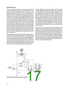
Shunt Connections
In some applications, however, supply currents flowing
through the power-supply return path may cause offset
or noise problems. In this case, better performance may
The recommended method for connecting the isolated
modulator to the shunt resistor is shown in Figure 17. V
IN+
(pin 2 of the HPCL-7860/HCPL-786J) is connected to the
be obtained by connecting V
and V directly across
positive terminal of the shunt resistor, while V (pin 3) is
IN+
IN-
IN-
the shunt resistor with two conductors, and connecting
GND1 to the shunt resistor with a third conductor for the
power-supply return path, as shown in Figure 19. When
connected this way, both input pins should be bypassed.
To minimize electromagnetic interference of the sense sig-
nal, all of the conductors (whether two or three are used)
connecting the isolated modulator to the sense resistor
should be either twisted pair wire or closely spaced traces
on a PC board.
shorted to GND1 with the power-supply return path func-
tioning as the sense line to the negative terminal of the
current shunt. This allows a single pair of wires or PC board
traces to connect the isolated modulator circuit to the
shunt resistor. By referencing the input circuit to the nega-
tive side of the sense resistor, any load current induced
noise transients on the shunt are seen as a common-mode
signal and will not interfere with the current-sense signal.
This is important because the large load currents flowing
through the motor drive, along with the parasitic induc-
tances inherent in the wiring of the circuit, can generate
both noise spikes and offsets that are relatively large com-
pared to the small voltages that are being measured across
the current shunt.
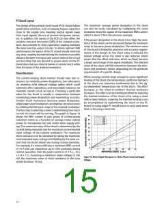
The 39 ꢆ resistor in series with the input lead (R2) forms
a lowpass anti-aliasing filter with the 0.01 ꢄF input bypass
capacitor (C2) with a 400 kHz bandwidth. The resistor per-
forms another important function as well; it dampens any
ringing which might be present in the circuit formed by
the shunt, the input bypass capacitor, and the inductance
of wires or traces connecting the two. Undamped ringing
of the input circuit near the input sampling frequency can
alias into the baseband producing what might appear to
be noise at the output of the device.
If the same power supply is used both for the gate drive cir-
cuit and for the current sensing circuit, it is very important
that the connection from GND1 of the isolated modulator
to the sense resistor be the only return path for supply cur-
rent to the gate drive power supply in order to eliminate
potential ground loop problems. The only direct connec-
tion between the isolated modulator circuit and the gate
drive circuit should be the positive power supply line.
FLOATING
POSITIVE
SUPPLY
HV+
GATE DRIVE
CIRCUIT
R1
D1
5.1 V
C1
0.1 μF
R2a 39 Ω
VDD1
VIN+
VIN-
VDD2
R2b 39 Ω
MCLK
MDAT
MOTOR
+
-
GND1 GND2
C2a
0.01 μF
C2b
0.01 μF
RSENSE
HCPL-7860ꢀ
HCPL-786J
HV-
Figure 19. Schematic for Three Conductor Shunt Connection.
17

 AVAGO [ AVAGO TECHNOLOGIES LIMITED ]