100
90
80
70
60
50
40
V
(200 mV/DIV.ꢀ
IN+
OVR1 (200 mV/DIV.ꢀ
THR1
(2 V/DIV.ꢀ
30
20
10
0
1
2
3
4
5
2 μs/DIV.
CONVERSION MODE #
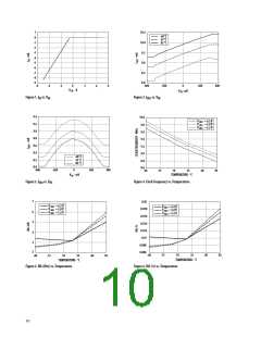
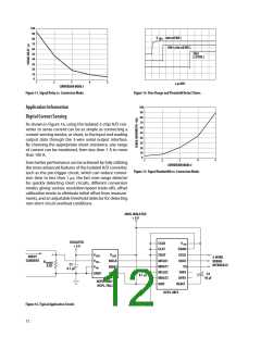
Figure 13. Signal Delay vs. Conversion Mode.
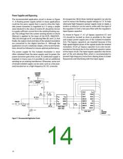
Figure 14. Over-Range and Threshold Detect Times.
100
90
80
70
60
50
40
Application Information
Digital Current Sensing
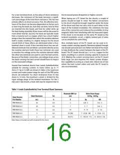
As shown in Figure 16, using the Isolated 2-chip A/D con-
verter to sense current can be as simple as connecting a
current-sensing resistor, or shunt, to the input and reading
output data through the 3-wire serial output interface.
By choosing the appropriate shunt resistance, any range
of current can be monitored, from less than 1 A to more
than 100 A.
30
20
10
0
4
5
1
2
3
Even better performance can be achieved by fully utilizing
the more advanced features of the Isolated A/D converter,
such as the pre-trigger circuit, which can reduce conver-
sion time to less than 1 ꢄs, the fast over-range detector
for quickly detecting short circuits, different conversion
modes giving various resolution/speed trade-offs, offset
calibration mode to eliminate initial offset from measure-
ments, and an adjustable threshold detector for detecting
non-short circuit overload conditions.
CONVERSION MODE #
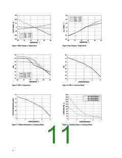
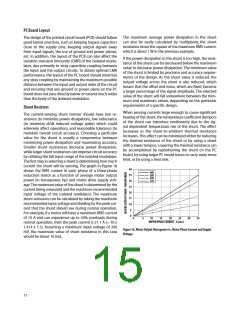
Figure 15. Signal Bandwidth vs. Conversion Mode.
NON-ISOLATED
+ 5 V
ISOLATED
+ 5 V
CCLK
VDD
CHAN
SCLK
SDAT
CS
CLAT
+
VDD1
VIN+
VIN-
VDD2
MCLK
MDAT
CDAT
INPUT
CURRENT
3-WIRE
SERIAL
INTERFACE
MCLK1
MDAT1
MCLK2
MDAT2
GND
R SHUNT
0.02
C1
0.1 μF
C2
0.1 μF
+
THR1
OVR1
RESET
GND1
GND2
C3
10 μF
HCPL-7860ꢀ
HCPL-786J
HCPL-0872
Figure 16. Typical Application Circuit.
12

 AVAGO [ AVAGO TECHNOLOGIES LIMITED ]