• Bit 1 – OCIEnA: Output Compare A Match Interrupt Enable
When this bit is written to one, and the I-flag in the Status Register is set (interrupts glo-
bally enabled), the Timer/Countern Output Compare A Match interrupt is enabled. The
corresponding Interrupt Vector (See “Interrupts” on page 56 ) is executed when the
OCFnA flag, located in TIFRn, is set.
• Bit 0 – TOIEn: Timer/Counter Overflow Interrupt Enable
When this bit is written to one, and the I-flag in the Status Register is set (interrupts glo-
bally enabled), the Timer/Countern Overflow interrupt is enabled. The corresponding
Interrupt Vector (See “Interrupts” on page 56 ) is executed when the TOVn flag, located
in TIFRn, is set.
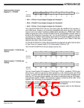
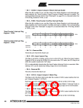
Timer/Counter1 Interrupt Flag
Register – TIFR1
Bit
7
–
6
–
5
4
–
3
OCF1C
R/W
0
2
OCF1B
R/W
0
1
OCF1A
R/W
0
0
TOV1
R/W
0
ICF1
R/W
0
TIFR1
Read/Write
Initial Value
R
0
R
0
R
0
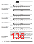
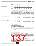
Timer/Counter3 Interrupt Flag
Register – TIFR3
Bit
7
–
6
–
5
4
–
3
OCF3C
R/W
0
2
OCF3B
R/W
0
1
OCF3A
R/W
0
0
TOV3
R/W
0
ICF3
R/W
0
TIFR3
Read/Write
Initial Value
R
0
R
0
R
0
• Bit 7..6 – Reserved Bits
These bits are reserved for future use.
• Bit 5 – ICFn: Input Capture Flag
This flag is set when a capture event occurs on the ICPn pin. When the Input Capture
Register (ICRn) is set by the WGMn3:0 to be used as the TOP value, the ICFn flag is set
when the counter reaches the TOP value.
ICFn is automatically cleared when the Input Capture Interrupt Vector is executed. Alter-
natively, ICFn can be cleared by writing a logic one to its bit location.
• Bit 4 – Reserved Bit
This bit is reserved for future use.
• Bit 3 – OCFnC: Output Compare C Match Flag
This flag is set in the timer clock cycle after the counter (TCNTn) value matches the Out-
put Compare Register C (OCRnC).
Note that a Forced Output Compare (FOCnC) strobe will not set the OCFnC flag.
OCFnC is automatically cleared when the Output Compare Match C Interrupt Vector is
executed. Alternatively, OCFnC can be cleared by writing a logic one to its bit location.
• Bit 2 – OCFnB: Output Compare B Match Flag
This flag is set in the timer clock cycle after the counter (TCNTn) value matches the Out-
put Compare Register B (OCRnB).
Note that a Forced Output Compare (FOCnB) strobe will not set the OCFnB flag.
138
AT90CAN128
4250E–CAN–12/04

 ATMEL [ ATMEL ]