Table 65. Definitions
BOTTOM The counter reaches the BOTTOM when it becomes zero (0x00).
MAX
TOP
The counter reaches its MAXimum when it becomes 0xFF (decimal 255).
The counter reaches the TOP when it becomes equal to the highest
value in the count sequence. The TOP value can be assigned to be the
fixed value 0xFF (MAX) or the value stored in the OCR2A Register. The
assignment is dependent on the mode of operation.
Timer/Counter Clock
Sources
The Timer/Counter can be clocked by an internal synchronous or an external asynchro-
nous clock source. The clock source is selected by the clock select logic which is
controlled by the clock select (CS22:0) bits located in the Timer/Counter control register
(TCCR2).The clock source clkT2 is by default equal to the MCU clock, clkI/O. When the
AS2 bit in the ASSR Register is written to logic one, the clock source is taken from the
Timer/Counter Oscillator connected to TOSC1 and TOSC2 or directly from TOSC1. For
details on asynchronous operation, see “Asynchronous Status Register – ASSR” on
page 154. For details on clock sources and prescaler, see “Timer/Counter2 Prescaler”
on page 158.
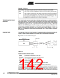
Counter Unit
The main part of the 8-bit Timer/Counter is the programmable bi-directional counter unit.
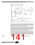
Figure 62 shows a block diagram of the counter and its surrounding environment.
Figure 62. Counter Unit Block Diagram
TOVn
(Int.Req.)
DATA BUS
TOSC2
count
T/C
clk Tn
clkTnS
Oscillator
clear
TCNTn
Control Logic
Prescaler
direction
TOSC1
bottom
top
clk
I/O
Figure 63.
Signal description (internal signals):
count Increment or decrement TCNT2 by 1.
direction Selects between increment and decrement.
clear
clkT2
top
Clear TCNT2 (set all bits to zero).
Timer/Counter clock.
Signalizes that TCNT2 has reached maximum value.
Signalizes that TCNT2 has reached minimum value (zero).
bottom
Depending on the mode of operation used, the counter is cleared, incremented, or dec-
remented at each timer clock (clkT2). clkT2 can be generated from an external or internal
clock source, selected by the Clock Select bits (CS22:0). When no clock source is
selected (CS22:0 = 0) the timer is stopped. However, the TCNT2 value can be accessed
142
AT90CAN128
4250E–CAN–12/04

 ATMEL [ ATMEL ]