ATmega64A
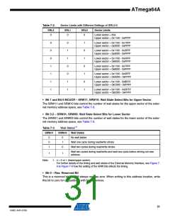
Table 7-2.
Sector Limits with Different Settings of SRL2:0
SRL2
SRL1
SRL0
Sector Limits
0
0
0
Lower sector = N/A
Upper sector = 0x1100 - 0xFFFF
0
0
0
1
1
1
1
0
1
1
0
0
1
1
1
0
1
0
1
0
1
Lower sector = 0x1100 - 0x1FFF
Upper sector = 0x2000 - 0xFFFF
Lower sector = 0x1100 - 0x3FFF
Upper sector = 0x4000 - 0xFFFF
Lower sector = 0x1100 - 0x5FFF
Upper sector = 0x6000 - 0xFFFF
Lower sector = 0x1100 - 0x7FFF
Upper sector = 0x8000 - 0xFFFF
Lower sector = 0x1100 - 0x9FFF
Upper sector = 0xA000 - 0xFFFF
Lower sector = 0x1100 - 0xBFFF
Upper sector = 0xC000 - 0xFFFF
Lower sector = 0x1100 - 0xDFFF
Upper sector = 0xE000 - 0xFFFF
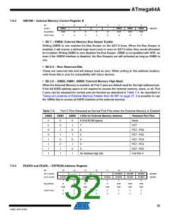
• Bit 1 and Bit 6 MCUCR – SRW11, SRW10: Wait State Select Bits for Upper Sector
The SRW11 and SRW10 bits control the number of wait states for the upper sector of the exter-
nal memory address space, see Table 7-3.
• Bit 3:2 – SRW01, SRW00: Wait State Select Bits for Lower Sector
The SRW01 and SRW00 bits control the number of wait states for the lower sector of the exter-
nal memory address space, see Table 7-3.
Table 7-3.
Wait States(1)
SRWn0 Wait States
SRWn1
0
0
1
0
1
0
No wait states
Wait one cycle during read/write strobe
Wait two cycles during read/write strobe
Wait two cycles during read/write and wait one cycle before driving out new
address
1
1
Note:
1. n = 0 or 1 (lower/upper sector).
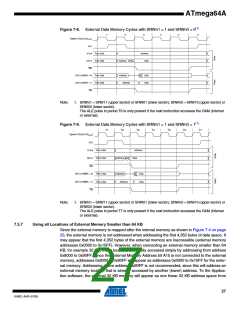
For further details of the timing and wait states of the External Memory Interface, see Figure 7-
6 to Figure 7-9 how the setting of the SRW bits affects the timing.
• Bit 0 – Res: Reserved Bit
This is a reserved bit and will always read as zero. When writing to this address location, write
this bit to zero for compatibility with future devices.
31
8160C–AVR–07/09

 ATMEL [ ATMEL ]