ATmega64A
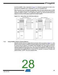
7.6.3
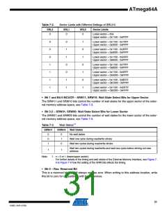
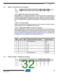
XMCRB – External Memory Control Register B
Bit
7
XMBK
R/W
0
6
–
5
–
4
–
3
–
2
XMM2
R/W
0
1
0
(0x6C)
XMM1
R/W
0
XMM0
R/W
0
XMCRB
Read/Write
Initial Value
R
0
R
0
R
0
R
0
• Bit 7 – XMBK: External Memory Bus Keeper Enable
Writing XMBK to one enables the Bus Keeper on the AD7:0 lines. When the Bus Keeper is
enabled, it will ensure a defined logic level (zero or one) on AD7:0 when they would otherwise
be tri-stated. Writing XMBK to zero disables the Bus Keeper. XMBK is not qualified with SRE, so
even if the XMEM interface is disabled, the Bus Keepers are still activated as long as XMBK is
one.
• Bit 6:3 – Res: Reserved Bits
These are reserved bits and will always read as zero. When writing to this address location,
write these bits to zero for compatibility with future devices.
• Bit 2:0 – XMM2, XMM1, XMM0: External Memory High Mask
When the External Memory is enabled, all Port C pins are default used for the high address byte.
If the full 60KB address space is not required to access the external memory, some, or all, Port
C pins can be released for normal port pin function as described in Table 7-4. As described in
“Using all Locations of External Memory Smaller than 64 KB” on page 27, it is possible to use
the XMMn bits to access all 64KB locations of the external memory.
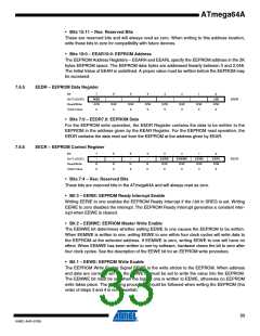
Table 7-4.
Port C Pins Released as Normal Port Pins when the External Memory is Enabled
XMM2
XMM1
XMM0
# Bits for External Memory Address
Released Port Pins
None
0
0
0
0
1
1
1
1
0
0
1
1
0
0
1
1
0
1
0
1
0
1
0
1
8 (Full 60 KB space)
7
PC7
6
PC7 - PC6
PC7 - PC5
PC7 - PC4
PC7 - PC3
PC7 - PC2
Full Port C
5
4
3
2
No Address high bits
7.6.4
EEARH and EEARL – EEPROM Address Register
Bit
15
14
13
12
11
10
EEAR10
EEAR2
2
9
8
0x1F (0x3F)
0x1E (0x3E)
–
–
–
–
–
EEAR9
EEAR1
1
EEAR8
EEAR0
0
EEARH
EEARL
EEAR7
EEAR6
EEAR5
EEAR4
EEAR3
7
R
6
R
5
R
4
R
3
R
Read/Write
Initial Value
R/W
R/W
X
R/W
R/W
X
R/W
R/W
X
R/W
0
R/W
0
R/W
0
R/W
0
R/W
0
X
X
X
X
X
X
X
X
32
8160C–AVR–07/09

 ATMEL [ ATMEL ]