ATmega64A
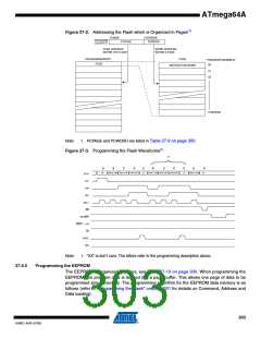
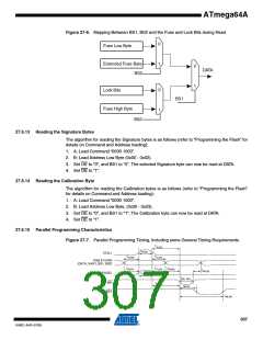
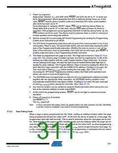
Figure 27-6. Mapping Between BS1, BS2 and the Fuse and Lock Bits during Read
0
Fuse Low Byte
Extended Fuse Byte
BS2
1
0
1
DATA
0
1
Lock Bits
BS1
Fuse High Byte
BS2
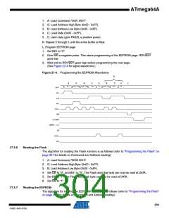
27.6.13 Reading the Signature Bytes
The algorithm for reading the Signature bytes is as follows (refer to “Programming the Flash” for
details on Command and Address loading):
1. A: Load Command “0000 1000”.
2. B: Load Address Low Byte (0x00 - 0x02).
3. Set OE to “0”, and BS1 to “0”. The selected Signature byte can now be read at DATA.
4. Set OE to “1”.
27.6.14 Reading the Calibration Byte
The algorithm for reading the Calibration bytes is as follows (refer to “Programming the Flash”
for details on Command and Address loading):
1. A: Load Command “0000 1000”.
2. B: Load Address Low Byte, (0x00 - 0x03).
3. Set OE to “0”, and BS1 to “1”. The Calibration byte can now be read at DATA.
4. Set OE to “1”.
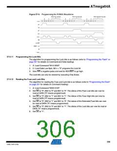
27.6.15 Parallel Programming Characteristics
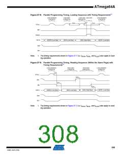
Figure 27-7. Parallel Programming Timing, Including some General Timing Requirements
tXLWL
tXHXL
XTAL1
tDVXH
tXLDX
Data & Contol
(DATA, XA0/1, BS1, BS2)
tBVPH
tPLBX
t BVWL
tWLBX
PAGEL
tPHPL
tWL WH
WR
tPLWL
WLRL
RDY/BSY
tWLRH
307
8160C–AVR–07/09

 ATMEL [ ATMEL ]