ATmega64A
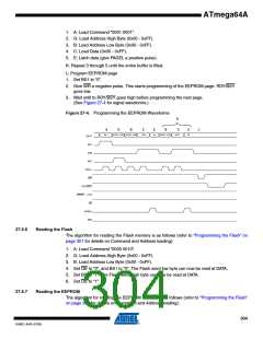
1. A: Load Command “0000 0011”.
2. G: Load Address High Byte (0x00 - 0xFF).
3. B: Load Address Low Byte (0x00 - 0xFF).
4. Set OE to “0”, and BS1 to “0”. The EEPROM Data byte can now be read at DATA.
5. Set OE to “1”.
27.6.8
Programming the Fuse Low Bits
The algorithm for programming the Fuse Low bits is as follows (refer to “Programming the Flash”
on page 301 for details on Command and Data loading):
1. A: Load Command “0100 0000”.
2. C: Load Data Low Byte. Bit n = “0” programs and bit n = “1” erases the Fuse bit.
3. Set BS1 to “0” and BS2 to “0”.
4. Give WR a negative pulse and wait for RDY/BSY to go high.
27.6.9
Programming the Fuse High Bits
The algorithm for programming the Fuse High bits is as follows (refer to “Programming the
Flash” on page 301 for details on Command and Data loading):
1. A: Load Command “0100 0000”.
2. C: Load Data Low Byte. Bit n = “0” programs and bit n = “1” erases the Fuse bit.
3. Set BS1 to “1” and BS2 to “0”. This selects high data byte.
4. Give WR a negative pulse and wait for RDY/BSY to go high.
5. Set BS1 to “0”. This selects low data byte.
27.6.10 Programming the Extended Fuse Bits
The algorithm for programming the Extended Fuse bits is as follows (refer to “Programming the
Flash” on page 301 for details on Command and Data loading):
1. A: Load Command “0100 0000”.
2. C: Load Data Low Byte. Bit n = “0” programs and bit n = “1” erases the Fuse bit.
3. Set BS2 to “1” and BS1 to “0”. This selects extended data byte.
4. Give WR a negative pulse and wait for RDY/BSY to go high.
5. Set BS2 to “0”. This selects low data byte.
305
8160C–AVR–07/09

 ATMEL [ ATMEL ]