ATmega64A
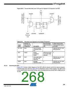
Figure 25-9. General Boundary-scan Cell used for Signals for Comparator and ADC
To
Next
Cell
ShiftDR
EXTEST
0
1
0
1
D
Q
D
G
Q
From
ClockDR
UpdateDR
Previous
Cell
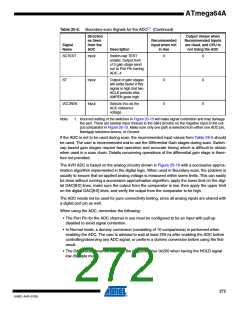
Table 25-4. Boundary-scan Signals for the Analog Comparator
Direction as
Seen from the
Comparator
Recommended
Input when Not in
Use
Output Values when
Recommended Inputs
are Used
Signal
Name
Description
AC_IDLE
Input
Output
Input
Input
Turns off Analog
Comparator when
true
1
Depends upon µC code
being executed
ACO
Analog
Comparator
Output
Will become input
to µC code being
executed
0
ACME
ACBG
Uses output signal
from ADC mux
when true
0
Depends upon µC code
being executed
Bandgap
Reference enable
0
Depends upon µC code
being executed
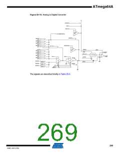
25.5.6
Scanning the ADC
Figure 25-10 shows a block diagram of the ADC with all relevant control and observe signals.
The Boundary-scan cell from Figure 25-6 is attached to each of these signals. The ADC need
not be used for pure connectivity testing, since all analog inputs are shared with a digital port pin
as well.
268
8160C–AVR–07/09

 ATMEL [ ATMEL ]