ATmega64A
same clock option as to be used in the final system. The enable signals are supported in the
scan chain because the system logic can disable clock options in sleep modes, thereby dis-
connecting the Oscillator pins from the scan path if not provided. The INTCAP Fuses are not
supported in the scan-chain, so the boundary scan chain cannot make a XTAL Oscillator
requiring internal capacitors to run unless the fuse is correctly programmed.
25.5.5
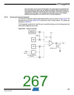
Scanning the Analog Comparator
The relevant Comparator signals regarding Boundary-scan are shown in Figure 25-8. The
Boundary-scan cell from Figure 25-9 is attached to each of these signals. The signals are
described in Table 25-4.
The Comparator needs not be used for pure connectivity testing, since all analog inputs are
shared with a digital port pin as well.
Figure 25-8. Analog Comparator
BANDGAP
REFERENCE
ACBG
ACO
AC_IDLE
ACME
ADCEN
ADC MULTIPLEXER
OUTPUT
267
8160C–AVR–07/09

 ATMEL [ ATMEL ]